
Like Danny suggested for resistors, you can use multiple caps (in parallel unlike resistors in series) to reach a desired total. So, you can get 4.5 uF with a 3.0 paralleled with a 1.5 or three 1.5s in parallel. Sometimes you can save money overall if you buy a larger quantity of the same small caps to make up a number of caps in the XO.
-
-
oh boy. I don't tread my posts! I wouldn't worry tons about the 60 ohm resistor. or just run 3x 20 in parallel. It is optional.
caps and resistors I'll use any readily achieved value which counts on parallel wiring.diVine Sound - my DIY speaker designs at diVine AudioComment
-
the AudioWorx
Natalie P
M8ta
Modula Neo DCC
Modula MT XE
Modula Xtreme
Isiris
Wavecor Ardent
SMJ
Minerva Monitor
Calliope
Ardent D
In Development...
Isiris Mk II updates- in final test stage!
Obi-Wan
Saint-Saëns Symphonique/AKA SMJ-40
Modula PWB
Calliope CC Supreme
Natalie P Ultra
Natalie P Supreme
Janus BP1 Sub
Resistance is not futile, it is Volts divided by Amperes...
Just ask Mr. Ohm....Comment
-
I'm looking at different types of caps. I've searched for quite a while and of course "opinions" run the gamut on whether they make a difference. I'm contemplating different brands. Dayton and Solen are obviously budget brands. Erse Pulse X looks interesting and has 3% tolerance. I'm also looking at SoniCraft. They are obviously much more expensive. Since I'm doing so many speakers, upgrading caps will get very expensive. I can gather some of the caps in the various crossovers are more important sonically than others. So, if I were to upgrade the more important caps to SoniCraft, which ones (please specify the uF amount) for the Ansonica's, the TM variant and the Marsala's would be the best to upgrade? I'm not entirely sure that the SoniCraft's make a difference, so I'm willing to hedge my bet and upgrade some but not all the caps. For the lesser important caps, have any of you noticed a difference between Dayton, Solen and Erse Pulse X? The latter really intrigues me, but it might just be the marketing.Comment
-
I don't know if it helps, but I believe these were straight Dayton Poly at the DIY Chicago event where they were so well received.
The theory goes that caps in series with the tweeter make the most difference - for the series Ansonica variant, that's a 25μF and 16μF - not small!
In the parallel variation, it's just a 10μF.
Does that help you find them in the other networks?
I'd also spring for the Mills resistors on the tweeter's pad (series/parallel resistor) something I think I've mentioned elsewhere. I'm never 100% sure I really note a difference but...
No idea on the Erse stuff, but at the prices I see on DIYCable, they're cheaper than Dayton Poly for similar values (looking at the 250V versions). Not sure if Erse has stuff direct at similar prices or not.
The theory goes that the Solen is a small step up from the basic Dayton Poly, and I suspect the baseline Jantzen would be too. You could step up to Jantzen silver or Z-Superior (did Jon use the Z's recently? I think he may have...) but yeah - expensive, and FAST.
For movies, I'm not convinced it's ever worth the difference. For sit-down music listening on quality recordings that have lots of dynamic range, I start to wonder. That's the only place I'd invest in costly caps. So for the Masala, probably save the money. Front stage? Maybe. If it'll be delivering music, maybe.
You could consider wiring everything together, soldering, then twisting the caps in and soldering, they're easier to remove - so you could build basic now and at a later time when you don't feel the impact of the cost, experiment.
CdiVine Sound - my DIY speaker designs at diVine AudioComment
-
That first sentence is the best part! So I don't live with regrets, I'll mostly go Dayton or Solen and just upgrade the few big ones.Comment
-
SPL Output
OK, I was asking about these on the PE forum and had some positive responses that prompted me to dig deeper. If you didn't see the thread over there I'm looking for some 2-way speakers for 80% music, 15% TV and 5% movies. I've read through this thread start to finish and felt my ponderings were relevant to the design (at least my understanding of the design) so figured I would post here as there may be others trying to make a decision on these before the drivers are all gone! Maybe this posting will even convince jagman to post his progress
I think cjd answered the questions I had after reading the thread with his graphs in his post above and so now I don't really have questions so much as I'm looking for some confirmation that I'm interpreting the information given correctly.
I have a receiver that is rated for 4-8 ohm impedance drivers and will do 100 Watts at 8 ohms into two speakers so should be me somewhere around 170 Watts @ 4 ohms (I think) in stereo mode. Based on post #266 of this thread (above), if I'm reading the post correctly, the drive will hit maximum excursion at 75W for 20Hz so I would indeed be speaker limited not amplifier, correct? Also if I read correctly, at the plotted 30W supplied power, another 2 m back (3 m total from the speakers) I'll still be at SPLs >90 db pretty much for the whole range (20Hz-20kHz) which, IMO, still seems like it should be as loud as I'd ever want to listen to them.
OK, so had to look up what a rumble filter is (e.g. highpass filter) but it seems like <20 would only apply to vinyl (which I don't have), LFE (my receiver, I don't believe, sends the really low stuff to the L+R), and maybe high-resolution audio (which I also don't have). So as above I'm still limited to the max excursion which occurs at 75 watts or >90db from my seating postion. For a work around it also appears as though I have some bass management available on my receiver so if I wanted to avoid the excursion issues in order to go louder I might be able to 'fake' some profiles for my receiver for full range, where I'm listening at normal levels or for a 40 Hz highpass "party mode" where SQ is less desirable than volume so that I can push the speakers harder. I can't actually think of a case where I'd want to push the speakers so loud that I couldn't spend more than a few minutes in the room but it's nice to know that I have a work around at my disposal.
Did I miss anything in my interpretation of the so-called "weakness" of the Ansonica design? Has someone that has built these find themselves wishing he/she could push them just a little harder? Thanks in advance.Comment
-
I think you have a handle on it. A receiver will send all content to mains set full range or large, but usually not mix in LFE if a sub is not present.
I listen to some pretty low stuff, and it's clear when you start to push them too hard. They'll get pretty loud.
CdiVine Sound - my DIY speaker designs at diVine AudioComment
-
Trying to design my box and making my own cutlist (I saw the version provided earlier). I'm currently planning to use the translaminate technique for the front baffle and the top. I'll be using a round port to keep these at a 34" height. I'm also planning to mitre the joints of the box although I'm still working out whether I get anything from mitring the baffle/top and fighting with the 1.5" vs. 18mm thickness so I may just end up using butt joints to attach these, but a 18mm rabet might be cleaner than a straight butt and easier than a mitre joint. Still working the details out. I am planning to change the profile of the cabinets by keeping the 10° angle of the front but 'filling' the void at the back. I know less sexy but I'm trying to decrease my overall footprint while maintaining the same volume and provide some toddler-safe assurances. I haven't decided whether I'll keep the baltic birch sides or use some other veneer. The translaminate front will be a feature I'll maintain from the original. I have some other ideas on how I might dress them up. And regarding toddlers, still trying to work out how I might improve the drivers toddler resistance by incorporating grills.
I must have been one of the last orders to Kevin for the drivers and had them shipped to my cousin in the States. I should be picking them up at my cousin's this weekend (also glad to see Erich at diysoundgroup.com will be keeping the drivers alive). I'll be starting the cabinets, hopefully before the end of August and picking up tweeters and cross-over components in September/October to help spread the costs out. Aiming to have them done before winter sets in by mid-December.
Before I make sawdust, looking for confirmation on a couple measurements for the cabinets.
- Is there a target width for the post-chamfer baffle? I'm thinking I'll leave some small amount outside of the woofer targetting something like 7.5" once the chamfers are cut. Does that sound correct?
- The lean back angle is 10°, correct? Couldn't find it explicitly stated anywhere, did the trigonometry to figure it out and back-calculated the length of the baffle, but some confirmation before I make sawdust would be good =)
- There are two drawings for the cabinet.
@divine-audio.com
post#497497
Using the two drawings I can surmise that the measurements are given along the z-axis/altitude, and not along the baffle plane, correct? And assuming I've successfully worked out the leanback angle I should be able to re-apply my not-quite-forgotten trigonometry lessons to figure out the corrected centres along the baffle plane.
Regarding grills. I'm struggling with how to approach this. I realize I could forgo grills as designed , however, I'd prefer to give some protection given toddler mentioned above. I've seen the methods for constructing frames out of MDF/HDF stock. The Anarchy has the unique problem of having a large xmax of ~12mm and a surround standoff of ~4.2mm which I think means I need to clear the baffle by ~17 mm. I realize this will result in some visual impacts and possibly audible impacts if I'm not conservative in the approach. Anyway, alternative examples using thinner materials such as wire would be appreciated. I think I can embed magnets in the translaminated ply's as I assemble to keep them hidden if I have a design goal for the grill so I'd like to work this out a solution soon (or make the decision to abandon it).Comment
-
10° it is.
I went for a full 3/4in chamfer near the tweeter, though a little wiggle room there. It definitely helps diffraction.
Baffle layout, just do the numbers along the baffle plane. It's close enough. I think I measured top down.
Grills, I would skip the chamfer and add wool felt behind the grill. Cut out around the tweeter with a square (1/2in thick felt) and just round around the Anarchy.
Been on vacation so slow to respond. In a coffee shop non Portland right now.diVine Sound - my DIY speaker designs at diVine AudioComment
-
Thanks for taking the time to respond. It's amazing how many details there are to work out when one is building an established design, let alone what it must take to design one start to finish [I imagine]. Anyway, talking through some of this is immensely helpful.
So, my initial interpretation of your grill+felt suggestion was incorrect because I was taking it in the context of your previous answers on chamfer at the tweeter. So I did a little more digging with keywords "grill" and "felt" to decipher what your comments on felt meant. For posterity, what I think you're saying is to use felt padding to cover the surface of the baffle (with a square cutout for the tweeter, circle for drivers) and cover the grill frame and felt in the grill fabric. So does this then negate the other comment on chamfering only near the tweeter? Is there a reason not to chamfer and use grills? A chamfer would result in a speaker that is perhaps a little more interesting looking. Maybe an Avalon-style cut for the upper chamfer? OK, maybe not as dramatic as some of the Avalon-style boxes, but if I adjust the baffle I can take off more at the top corner (1.5~2.25 inches from the top corner in either direction) and taper it off by the first Anarchy driver leaving space for a grill around both the tweeter and drivers. I would make up the extra material cut-off by making the outside baffle laminations thicker (2.25" and 3" for the outside two pieces instead of 1.5" in the centre span). If nothing else that would add some architectural type interest over a straight box and keep some of the translaminate from being covered with grill cloth.
I'm also considering an access panel for the rear of the speaker. As this will be my first assembly it's making me a little nervous to close it all up and not be able to "reach" for that cross-over at the bottom that isn't quite working etc. Thinking about it now though, this adds a fair amount of extra work to the cabinet so I find myself rethinking whether I really want to do this.
Anarchy drivers are on hand. Plywood is taking up space in my garage. I even managed to make some sawdust over the weekend. I've got some rough cut panels for the bottom and back and I even have the sides including 10° side. I ordered some plastic resin glue so I am hoping to get started on gluing up the baffles this weekend.Comment
-
I've had some progress. As indicated in my previous post I have sides cut out to size, back, bottom rough cut. For the sides I cut out large rectangles and used a jig to cut them in half resulting in two equal four-sided trapezoids. As I remembered to account for the thickness of the saw kerf, this worked out rather well.
Here's the jig/sled I used for cutting the 10° angle for ripping the side panels.
Even more to my amazement it worked
On the long weekend I ripped the 22 pieces of plywood for the baffles. I cut 11 pieces total for each baffle, with the outside pieces ~3" and the next pieces about 2.25". The target width is still 9" so I ripped the centre piece to ~11mm thickness. The sides will make up the 12th and 13th slices respectively for a final thickness of 18mm*12 + 11mm*1=227mm = ~9 inches. Here they are stacked before glue up.
The thicker outside boards will allow me to take a larger chamfer at the tweeter and probably create some headaches with cutting out the woofer holes. I'll probably need to use a dado to trim the extra material around the woofers and create some extra work in fitting the braces. I'm also going to need to chamfer the back of the cutouts by hand as a router won't fit in there now (that's what rasps are for!).
The glue up went pretty well. I used DAP Weldwood Plastic Resin glue for it's longer open time and apparent resistance to creep. It's a darker colour than the normal yellow wood glue but it doesn't seem to be so dark that its really visible. It's my first time using the glue. You mix the glue powder with water by weight. I did a 100g the first round and only managed to half finish the first baffle. The following day was a little cooler so I had more working time. I did a batch of 250g and then another 60g when I ran out again! I clamped the two baffles side by side and managed to not glue them together. There's enough length on each piece to cut the length needed for a baffle and top.
I flipped the clamps up on their ends once set to wipe the excess glue
CJD indicated that he used a random orbit sander to level his boards. I used a hand-plane and cabinet scraper followed by a sander. This method also creates far less dust than a sander alone. I don't have a great sander but I've used a plane to level planks many times. I made a 'T' brace stop for the baffle and did the work on my table saw. I had the blade catch once or twice and had enough force behind the plane to pull the saw up onto two legs. Scary. I need a proper wood working bench for planing but instead I'm making speakers.
I'd recommend getting the glue up done as close to the time of ripping as possible. Waiting too long will result in some bowing which is not desirable. I had some strips that were bowing almost immediately.
Next steps I'll start cutting baffles and top to length and working on a template to route the circles for the drivers although I still don't have the tweeters on hand.
Comment
-
Awesome! Thanks for being the guinea pig!Comment
-
-
I love that shot of the nice clean flat baffle! Dang nice jig for the cuts too.
I know I'm not always the best at making my designs usable by the extreme novice, but the build threads that are successful usually show some really nice ingenuity and work - the builder actually gets to contribute something to making a successful build and helping others...
CdiVine Sound - my DIY speaker designs at diVine AudioComment
-
I haven't been sitting idle. I've been making some pretty good progress with some not-unexpected slow downs. The slow downs have revolved around the baffles not being quite square on the sides from the glue-up. I've re-ripped everything on all sides, cut the baffles and tops, cut the mitres, cleaned up the mitres, and did a mockup of the clamping.
The profile of the top looks cool from the back. Keep in mind that the front baffle has the same profile on the inside wall.
The mitres were pretty good but there's some slope in my saws mitre gauge, possibly some variations due to using thin-kerf blades and needing to remove my stabilizer disc to cut the full depth I could (e.g. blade flexes slightly). Also, full depth wasn't quite all the way through and need to finish with saw and chisel. The clamp-up revealed that I might have some problems with glue. In the end I wasn't happy with how the mitres were fitting so I lay the top on-top of the baffle, lined the mitre faces up close and smoothed it over with the plane. This is commonly done for scarf joints in guitar necks. Worked well in this application too. My saw had it close, the angle was correct, and the planing just straightened out the faces a touch without affecting the final angle.
I've received parts! Yay! One inductor sent was the wrong gauge and I ordered an incorrect inductor that was for the other version of the cross-over (I'm doing the parallel version - someone had to do it, and I figured it had fewer parts). So shipping back and hope to have the correct parts in a week or less. This is my first endeavour into DIY speakers and I must say I am blown away by the quality of the parts. The drivers, the MASS of the inductors. I just get the feeling that I can't help but build a really high quality speaker, like I can't fail. Well, hopefully my cabinets are consistent with the quality of the rest of the parts.
I had one day to work this weekend and managed to get the driver holes mostly done. I was thinking about making a circle jig myself but opted instead to buy a Jasper Jig. On my way to Lee Valley I stopped at my local HD to get some MDF for grills. I met a fellow in there that was getting some 3/4" BB ply. I suggested that he try another local specialty store (much cheaper there) and we got talking. He was building some speakers for a colleague based on a MarkAudio design (I hadn't heard of them until then). Small (audio) world apparently.
In regards to the circle jig, I figured I could spend the better part of a day tuning my jig to get the diameter holes I needed, or I could just buy the jig and finish making the holes. Well today I finished with the router at least, but still don't quite have the holes. Remember the profile of the baffle? Well I can't get through the thicker pieces on the sides so the cutout pieces are still holding on. I need to open the recesses anyway so I'll probably just use my dado blade to trim the ridge flush to the baffle, effectively finishing the driver routes where my bit could not penetrate the full 2.25". I made it through the 1.5" parts though and the tweeter hole came out nice. Since the back of the baffle is uneven I'm going to need to use a rasp or spokeshave (I like hand tools to chamfer the openings, no way to get a router bit on there. Sorry, no pictures yet from today.
Other thoughts: I think I'm going to use a 3" port and place it at the bottom near the front. That may change yet as I'm back to putting some sort of door for the back to get the cross overs in. CJD, in one post you mentioned that you were considering leaving the back, or part of the back removable. Did you go through with this?Comment
-
The entire back is removable on mine. I dado'd the back for it, so it's got a foam seal and is just screwed in. Works like a champ.
This is looking incredible. If you do a removable back you can start with a port on a panel, and replace it with a solid one if you decide to move to the front after all. If you move to the front, it would probably be worth cutting a ring that fits snug around the outside of your port tube, glue it in place inside, stick the tube in, then through-route with a flush-trim and finish with a 3/4" roundover so you have that lovely ply treatment for the port face.
I've found I like the hand-tools on the Nebbiolo build a lot, and you can do a lot with them in weird places. I'm even drilling holes for the wires to the mid chamber by twiddling the bit between thumb and fingers.
CdiVine Sound - my DIY speaker designs at diVine AudioComment
-
So as indicated in my previous post, I got the driver holes routed out. I used a jig saw to cut off the "wings" and free the openings. Quick cleanup on the wing sections and I had some pretty good looking holes. I grab enough drivers to fit up an entire baffle and.... drum roll.... just a hair to proud... darn. So I told myself that it probably wasn't going to make a difference. The tweeter and woofer were proud of the baffle by about the same amount and my plans to add grills will cover this up and probably introduce new reflections that might be even worst than whatever problems I had introduced with the baffle. Well, I told myself all those things and I just couldn't let it slide.
I've seen a number of posts (not necessarily here, but definitely on other forums) where people indicate that they don't have the driver cutouts quite deep enough and I see a lot of people live with it because they don't know what to do. Going to deep can be OK because you can add sealing tape to raise it up a bit. Going to shallow will always leave a lip. What to do? Cut yourself a disk the same size as your opening. Put the disk in the driver opening. Set your depth stop to your zero depth, and then re-measure (you got it wrong the first time right?) your desired off-set depth. Re-run your counter sink circles.
I had the added problem of having baffles that are 1.5" thick that stand 1.5" off my bench because of my "wings." My solution was to sandwich my new disk with some of my cutouts which was still to short. I added screws as feet that I was then able to adjust the screws to level the disc with the baffle. I used a piece of tape around the disc before running the router to get a snug fit. The corrected counter-sink resulted in perfect fit of all the drivers. I was able to make one jig for the woofer and tweeter to reuse for each opening.
Here's my discs with feet for the woofers.
For the tweeters.
And the driver fit:
I've started with the rasp on the backs of the baffles so the woofers can breathe and I levelled the back of the baffle behind the tweeter using dado blade so I can seal it off. I've also dadoed the back of the baffle for the braces at a 10 degrees. I keep thinking I'm close to being able to start gluing up but I keep thinking of more things to do. Getting closer now!Comment
-
That looks narrower than my build... :P
looking good though!diVine Sound - my DIY speaker designs at diVine AudioComment
-
I always wanted to do a translam build and you progress is reminding me why. I have a psuedo-translam part of my sunflowers but it's not nearly the same thing. And now that I've sold my Sunflowers to a buddy, it may be time to some Ansonica for me as well. Hmm...Comment
-
The baffle as I'm putting it together needs to fit "inside" the side panels so my photos as show are still short 1.5" (or 36mm...) of my final baffle width. That said I think I lost a little more material squaring up the baffles so I believe I'm coming in under 9" but somewhere north of 8.75". I figure 4 mm under is better than 5 mm over? Probably all a wash in the end.
I made the side panels deeper on either side (each side has laminations 2.25 and 3.0 inches deep stepping out from the 1.5" middle span) to support doing a faceted like cut away something ~2" tapering off to zero before the woofer. Plus grill and felt. If I understood what I've read correctly, I believe the grill and felt negate whatever benefit I would get from a chamfer/facet. I don't believe there's any harm in including the facet (?), I'm planning to do it for appearances/interest.Comment
-
This is SO fun to watch someone else do all this work... and get to see the results, if not hear them...the AudioWorx
Natalie P
M8ta
Modula Neo DCC
Modula MT XE
Modula Xtreme
Isiris
Wavecor Ardent
SMJ
Minerva Monitor
Calliope
Ardent D
In Development...
Isiris Mk II updates- in final test stage!
Obi-Wan
Saint-Saëns Symphonique/AKA SMJ-40
Modula PWB
Calliope CC Supreme
Natalie P Ultra
Natalie P Supreme
Janus BP1 Sub
Resistance is not futile, it is Volts divided by Amperes...
Just ask Mr. Ohm....Comment
-
I've made some progress. Long post follows. I won't bring up all my new little mistakes to keep it shorter Now where did I leave off...
I've got the backs of the driver cutouts chamfered. Because of my weird baffle profile there was no way to do this with a router - at least not my router. If you look closely at the photo below you can see that I actually removed quite a bit of material. This was a fair amount of work with rasp and chisel to carve it out - more time than I care to admit but went faster as I grew more accustomed to the working angles and material. Sharp tools help. My original plan was to use my table saw and just level the back of the baffle near the drivers to get an even chamfer all the way around with the rasp, but with the driver cutouts and the way I'm assembling the box I have less than 1/2" of plywood on eitherside of the driver cutouts - that would be four pretty delicate spots on the Baffle. The 3" baffle depth at the sides add a fair amount of stability and with the time of year, the time it's taking me to complete all the parts for final assembly, I'm noticing that the plywood is moving a bit - but the baffles not so much. There's just not a whole lot of material at the side of my driver routes until I get the sides glued onto the baffles. So rather than chancing making the baffles less stable, I rasped and carved chamfers and ramps. Got a lot of good practice with a chisel in my left hand as well. I left nodules of wood untouched below the screw mount points which should allow for me to add inserts in the future if I need to (helicoil style ones at least). I'm planning to use wood screws but I suspect screws into the ply-ends is a little like screwing into endgrain on wood so I don't have a lot of faith in the long-term hold if they are removed a bunch of times. The removable backs should all but alleviate those issues. I'll pre-drill the holes, thread the screw in, back them out and then squeeze a few drops of super glue or thinned epoxy to harden the wood threads. Went to see if my screw heads would fit the countersink.
I elected to glue up window style braces for the box because:- my table saw is the best tool I own and it was easy to get repeatable cuts/dimensions of the same length using the slide jig I already have.
- I did not fancy using the jasper jig to cut a hundred (OK, only like 30) little holes. The jig works very well but is also very good at filling my garage with sawdust.
- I like conserving wood where I can and window braces are a more efficient use of material.
I glued them up and used pocket screws to hold during assembly and then clamped the completed assemblies together. The screws didn't hold on their own as well as I would have liked so I had to clamp overnight. Why use screws at all you say? Well I have limited number of clamps and doing this type of clamp-up without a bench surface, bench dogs and vise isn't super easy. I'm using Weld Bond plastic glue which has the advantage of long open time and no creep, but it basically requires overnight clamping to cure at ~70°F (~21°C). The resulting joint of screw plus clamp is very strong.
The baffle of the Ansonica has a 10° backwards slope, and as a reminder, I've built my cabs with a straight back (deeper at the base than the top). From top to bottom, each brace is a little longer than the last. I've cut dados in the back of the baffle to slide the braces in (80° angle to the front so that I wouldn't need to angle the fronts of the braces) and will dado the back frame for the weather stripping seal on the removable back to fit the back of the braces. Based on my volume calculations I was a little over on my volume (~1.5L) in comparison to what I calculated for CJD's box so I think this will actually bring me closer in line to my target volume. I also need to throw in some cross braces in the space between the bottom and the lowest brace seen here, including some way to help support the port which I'm still planning to pass through the bottom.
Oh, and I got the tweeter cover on the back which was a riveting process of gluing a block of wood the back. The main thing was using a lot of glue so it would be self sealing but not so much so it wouldn't drip all over my basement floor (and from one of the pictures above I see I have some cleanup in route to do).
The frame for the back opening is not be made from window braces because my pocket screws + glue would not allow for a dado through the cross members and I think it will be more dimensionally accurate using a solid piece resulting in a potentially better seal than cutting out the windows. I want the accurate dimension to make sure I can get a good seal without an overly thick gasket material for the back. I don't have a photo with the finished dados for some reason but this shows how it goes together. I still need to cut out the windows with my jig saw.
I've also done dry fit test and only had to trim up one brace on each. I then started baffle layout to figure out where I was going to embed magnets. I'll be embedding the magnets either using a forstner bit behind the baffle, or using a biscuit jointer to fit it between joints. Here's the baffle at it's full width.
And here's the profile of the dry fit:
This thing is going to be heavier than I ever imagined with drivers in. Still not sure what I want to use for feet. I was thinking of putting some 1/4-20 inserts and using some self leveling furniture feet. I've never dealt with a speaker of this size before. How stable is is a 9" wide foot print? Now how stable is it with a toddler or two around? Will a plinth or wide feet standoffs be necessary? I see a lot of people using a metal cross piece with spikes/feet offset from the speaker body. Anyway, might not decide that until I've got one of them glued up to see how it feels.
Oh, and I'm having trouble sourcing screws for the Anarchy driver. Lee Valley has some nice black wood screws - 1" length, nice coarse threads, and reasonably priced. However, the heads don't fit in the countersink. Before I spend $20 on screws ordering screws from Solen, any suggestions on where else to look? Haven't seen anything like what Solen has except at other speaker sites. Also Reports the correct diameter? I was going to use the Private Messages from Lee Valley but I think Reports would work.Comment
-
if you have decided not to use Hurricane style inserts....I prefer to use Black Square drive wood screws.
I have had the unfortunate experience of walking out of the Phillips screws & scratching my wood. You
are probably too careful for such an accident....just a THOUGHT.
good work so far. The chisel & rasp sound very familiar.8O
good luck...I am impressed.Comment
-
Oddly enough, in Canada most wood screws sold separately are square/Robertson drive by default, but for whatever reason the ones I got from Lee Valley (a Canadian company) are Phillips. For pocket screws I used GRK cabinet screws which are Torx drive (because what the hey?). Too many options.
I'll have to check my screw supply to see if any of my "silver" Home Depot pan head wood screws fit the countersink. My thought is 'no'. I thought it would be a standard size but looking at it now, it seems like really narrow opening for the counter-bore relative to the shaft diameter (perfect for the Allen head screws from Solen/PE). The #6 screws I got for the tweeter fit the counter bore, but I feel like their threads wouldn't hold the weight of the anarchy well enough. There's a NAPA auto parts down the street so I may go check out what they have in terms of machine bolts. I know they will at least have Helicoils and I need something for the door seal still. Hurricane nuts would be more difficult to implement on the backs of the drivers due to window bracing blocking the back of some of them. Not impossible to overcome but I was hoping to go with easy first (e.g. wood screws) - but easy is proving difficult to source locally. Wish I'd sorted this before my last order to Solen.
Thanks for the encouragement.Comment
-
That's looking awesome.
I can not say how often I've gone "oh crap" and had to resort to brute force and an odd assortment of tools to solve things. Works out in the end.
CdiVine Sound - my DIY speaker designs at diVine AudioComment
-
Why is it the little details that always take the longest? I haven't made much progress as I'm getting caught up on the details that will help the glue-up go smoother. Maybe. Hopefully.
Keeping the grill hardware hidden and seamless. Sounds easy enough, right?
The assembly I've selected consists of rare earth magnets in ring and rod form. The ring magnet is embedded in the baffle, and the rod magnet sticks out from the grill. This magnet assembly has an interesting property where the poles are reversed and repel each other at first until the rod magnet is inserted through the ring magnet wherein the poles are now aligned and the assembly hold is really quite strong. The disks are 1/2" diameter with 1/4" diameter hole and the rod is 1" long. The reason I went with this assembly vs. say opposing magnetic disks, which likely has equal opposing hold power, is that when mated, the rod will be 1/2" into the bafflle and provide a significant resistance to shearing off the grill in addition the magnetic clamping force to the face of the baffle.
This type of magnet assembly has some other neat properties that don't apply to my baffles. With the poles are aligned the disk will sit nicely at either end of the rod magnet and will easily slide from one end to the other. In the video you can see initially that the magnets will rest at one end or the other of the rod. This is how I will be using them. If you reverse the direction of the poles then the disk will sit in the middle creating a magnetic spring from the opposing poles. This creates almost a cushion or spring. You can see this at the end of the video. If the disk approaches the end of the rod it suddenly repels - and well you can see it at the end of the video.
For the baffle mounts, the 1/4" holes will be fairly unobtrusive on the front and easy to cut plugs for should I reach a point where I can run the speakers without grills. The unfortunate part is my wife actually indicated that given the work that has gone into the baffle and the results of the translaminations, in addition to the nice looking drivers - it would actually look good, kind of industrial... without grills... never would have guessed I could have gotten away with it. Alas, toddlers and their prying fingers are about. Best to stay safe in this case I think.
So magnet mounting points are centred above the tweeter, below the bottom woofer, and two on either sides of the woofers. Spacing was worked out to avoid the facets I am planning on the front. Magnets in the centre of the baffles have been installed using a 1/2" Forstner bit and a bit of dowel will be glued behind.Now I sanded the dowel piece down so that it will not put a lot of stress on the translaminations. I will also orientate the grain on the dowel so that if the wood in the dowel expands will will push along the length of the grain. I didn't take any pictures of this apparently.
Magnets on the sides were cut using a biscuit joiner bit and attachment on my fixed base router. Clamping the baffle sides vertically I used my bench top drill press to put the 1/4" hole in. I put the magnets in the slots and filled the space with putty epoxy.The putty epoxy should hold the magnet in firmly and keep the holes from flooding when I do the glue-up.
The magnet nubs sticking out will be the part embedded into the grill frames.
The assembly will be done using biscuits to strengthen the butt joints and assist with lining things up. I installed nine biscuits per side, plus a few more on a couple of the unshown surfaces. The biscuits worked as desired and everything lined up well.
I am really happy with how it interlocked together with the biscuits. A couple clamps was all it took to stand it up. It was enough to hold it together for me to carry the assembly down to my basement. You can see the six 1/4" holes for the magnets on the front baffle.
That little stack of boards on the side are the cutouts for the window. I am thinking about attaching them to the backs of the door.
Another profile shot of the.
A few things to finish up on the fit but overall I am really happy with how they are shaping up. I need to work out the port still, but I am really close to being able to glue these things up. Hoping to have these things together by the end of the month. That might actually happen.Comment
-
Question, if I were to put the inductor coils in this configuration it's OK, right?
These are the components for the woofers.
Edit:
OK, I found the source I based this on. I had seen a number of versions of the image at the bottom of Troel's test page found here. Based on that page I would guess that I am OK. I'm guessing there might be better options if I spread board out but to put the board in the bottom I'm limited to an approximate 6"x6" board because I have my port coming in the bottom of the speaker. The width of the board in the image is about 6". I will likely place the tweeter components above the top brace window behind the tweeter. What would be the lesser evil, a bit crowded like the photo above? Or more spacious, but possibly closer to the woofer magnet?Comment
-
I usually try to put the inductors at the corners, but your layout looks reasonable. It's always a bit of a puzzle.
CdiVine Sound - my DIY speaker designs at diVine AudioComment
-
I have a serious itch to build these. But where to put them...
Great job on this design.Comment
-
-
I thought you were itching to use them in a three way design? :-)Comment
-
I haven't posted updates for a few weeks which means a big post of updates follows.
I've completed the vent/port. I've seen other people do it this way. Basically cut the angles, use ABS contact cement on each joining edge and hold together tightly for ~30 seconds. The results seem rather sturdy. I used my table saw to make the initial cut. but all my cuts were angled so the blade never quite took it all the way through. I finished the cut with a hacksaw and cleaned up the face of the cut with a block plane.
Also, if you're going to do this safely, you should use a jig to clamp the pipe so it doesn't roll on the table and bind in the table saw blade. I had a scrap of wood that I had done some test cove cuts for a brick mold profile (didn't use it on the brick mold in the end) that matched the profile of the pipe perfectly. A V-notch in a board would likely work just as well.
According to the design, I needed 18" of pipe of the 3" I.D. pipe for the proper tuning frequency, and I had ~36" pipe to work with, minus table saw kerf for however many cuts I needed, plus the assumption that porting to the bottom was good for some length of pipe. At one point I had found an estimate (somewhere...) of 1-2" of equivalent length for bottom ports. So I figured I had 2-4" to spare assuming I didn't need to redo any cuts. I was hesitant to just cut a straight piece to start as a test fit because I didn't want to waste any because 1-2" waste per side can quickly go away with one bad cut so I started with a profile matching the 10° slope on the front. My first cut was a little collar to put in the mounting plate ~3/4" thick and cut the face to 5°. Next mated the matching 5°face on the next section and made two more cuts at 20° (three cuts, but each cut makes two faces resulting in mitre angles of 5°+5°+20°+20°+20°+20°=90°). Turns out I had enough clearance from my starting point that I could have left the initial section as a straight piece and then made the cuts for the 90° bend.
So, I get to this point and think to my self, "self, this is going great, this isn't hard at all." When I finally stopped to figure out how much more I needed for my final cut I realized I already had a tube length of ~16", plus the opening to the floor should be equivalent to another inch or two so I'm already closing in on 18" needed BEFORE adding an exit bell/flange to the internal opening. I had anticipated needing another piece in order to end on a straight section to easily attach the a bell using the circle cutter.
I didn't get a photo of if but I used some crafting foam paper (?) as a gasket for the mounting board an the base of the speaker. Just trimmed to the size of the mounting board and screwed the board on. That way if I need to redo it I can hopefully reach the screws and remove it without scraping glue or sealant.
No matter, having the opening end with an angle cut has a similar result to a bell; it also achieves a higher cross sectional area which should reduce chuffing/port exit noise by reducing exit velocities. The bell will be done by tracing the elliptical cross section onto some plywood, hogging out the middle section with a Forstner bit and cleaning up with a rasp. The second one can then be made with the router templating bit. The roundover for the final bell shape can then either be done with a router bit, although I'll more likely use a rasp/file so that I can make the exit roundover more consistent with the curren pipe direction. A friend has an audio measuring kit for work so I'll see if she has the equipment to do an impedance sweep needed to verify the tuning when she [hopefully] comes to do the response testing. I'll leave it as is until I listen to it and see if I can build it into the appropriate tuning length later. Here's to hoping the woofer crossover fits below the port without impeding it Here's the dry fit photo.
I also routed a round area into the back panel for my binding posts. Instead of cutting the circle directly I cut out a template and using a templating bit (has a bearing on top) hogged out the middle to about 12mm to get a matching birch layer that isn't all the way through to the window plug beneath. Needs a little sanding to get rid of the swirls. In the second photo you can see the rear window brace cutouts that I've put onto the back which means the back will only go on one way. It also provides a convenient mounting point for my carpet.
Before starting glueup I did another round of dry fittings for each speaker. I pre-drilled braces for wire runs to each driver/cross over from the speaker terminal posts. And this is where I really started to understand the extent of the problem in working with translaminated plywood. If you're thinking about doing translam baffles. Don't. It's a pain in the word that this forum will probably bleep. If you're set on it, I have some tips.
Plywood is made of thin strips of wood. If you cut an edge you have wood edge grain and end grain exposed. Depending on the grain orientation, the individual layers will want to expand either along the length of the plywood, which it can't really do because alternating layers more or less restrict this, or width of the plywood, which is only limited by the glue penetration of adjacent layers. So if you start layering up a bunch of layers and glue them together in August on a hot summer afternoon, and go to do your final cabinet glue-up on a cold December afternoon, don't be surprised if your initial measurements are a little bit off. See my previous post about fixing the rabbet for the driver AFTER doing the cut out. Just assume that I had to follow those steps again to fix a round rabbet that was now slightly oval due to baffle contractions.
Anyway, after the dry fit, re-trimming braces, some minor adjustments with hand plane, we have this:
Unfortunately I forgot to pull out my camera and get some better photos, but I did remember to grab at least a couple with my cellphone. I had 14 clamps, 6 on loan from a friend, several hand clamps that I was able to use on the back part of the cabinet, and 110lbs of dumbbell weights.
I did a similar clamp layout with second speaker and think I actually did a much better job of the clamping... but I forgot to take a picture. As with any glue-up, take a rag, get it wet, and rub off as much glue as you can and save yourself a lot of work down the road.
Again, I'm using a plastic resin glue that is made by mixing a powder with water (in my case I'm using the one called Weldwood, made by DAP). It has a long open time and also a long clamping time. I mixed up 300 grams of powder for each speaker, applied to each edge using a two inch paint brush which helped get everything on relatively quickly. I also used the glue to seal-up the backs of the baffles and with only a few tablespoons of waste. I credit the glue with making a complete glue-up possible in one go.
Once I had the speakers glued it was time to start the facets. I used a skill saw with a wood guide placing the sole on the side of the speaker for a 45° degree cut. I made the cut within an 1/8" of where I wanted the final surface and brought it down with a hand plane. The lower facets are actually at about 55° from the sides (steeper than my skill saw can go) so I had quite a bit of correcting with the hand plane. My garage was pretty cold at this point.
I'm very happy with the results. If you've been following you may remember that the thicker boards used on the baffle edges means that I was able to maintain the 1.5" baffle thickness on the facets.
So not exactly to CJD's spec but hopefully close enough. Also hoping to do some verification testing when my friend comes so we can see how close I am (or not).
I'll get the second speaker caught up to this point, cut the grills to size and actually mount the grills for the final sanding of the facets and sides so that the angles match up correctly (you can see the magnetic mating points in the photos above). I'm visiting family for the holidays so I brought the cross over parts with me. Hopefully I'll get cross-overs done in the next week.Comment
-
That looks awesome with the translam cut that way. I just may have to do the 3-way with the Anarchy that way! (I am seriously considering an all-metal driver partner to the Nebbiolo - i.e. 2nd order slopes, yadda yadda.)
diVine Sound - my DIY speaker designs at diVine AudioComment
-
I need to hear what they sound like, going to take it easy though with mdf. 1" front baffle, 3/4" sides/top/back and 1/2" for the slot port.
Maybe BB ply for internal bracing.
20 liters was the going rate (per-speaker) when I bought them back during the summer. So will double check and work to that.
mdf: the lighter, whiter color mdf is easier to work with, less dust and paints better. This shelving board is from local lumber yard $2 a foot.
Oh there's a place for them, its the other speakers that are there now I don't want to part with.
Comment
-
Box is on the large size as-is, need to square up panels anyway.
That driver works in a small box, unless the listed parameters are wrong.
If I remember correctly, 20 liters is about the limit.
sim here is only one driver.
Comment
-
My box tuning takes the crossover into account and is an EBS alignment, assuming a little room gain (it would be unusual to not have some at these frequencies)diVine Sound - my DIY speaker designs at diVine AudioComment
-
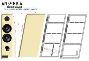
Thanks for taking a look - been working to this: http://www.divine-audio.com/wp-conte.../boxLayout.png
Was going to use the slot port design on right, just want to make sure the box is close as possible.
Can I use 12-3/4" x 32-1/2" x 7.5" ID and use bracing as shown?
Need to order the tweeters, there's store front somewhere?Comment
-
Internal dimensions are right. Bracing, yup.
I got my tweeters from Madisound.diVine Sound - my DIY speaker designs at diVine AudioComment
-
OK done! Always good to talk to the MS guys!
cdj May I ask where is the xo part list? I though it was modified a bit once, but don't really know.
Thinking that starting a "MDF Ansonica" Thread is in order also.Comment
-
The final versions are on his website. For what it's worth, I'm doing the parallel version. I think the other builds used the series version.Comment
-
Man, I'm appreciating all our hard work. That looks tough working the end grain of the ply. These are coming together nicely. :TComment
-
Thanks knowledge..... trying to wrap my head around the xo designs, what the impedance for the parallel - 4ohm?
OR Is the Parallel xo a 2-way vs. a 2.5?
Comment
-
Both versions are 4 ohm, both are 2.5 way designs. CJD has included optional LRC loops for each to stabilize the impedance at about 4 ohms which is beneficial to some amps (e.g. more stable load across all frequencies). Generally, the DIY community will conservatively rate a speaker 4 or 8 ohms, based on where the lowest impedance resides (as observed in the impedance plots) . I think I've seen a few 6 ohm designs as well.
This is my first build, and beyond understanding how to read the schematic in order to put it together, the workings of it are more or less still a black box to me. From my own reading, the series and parallel crossovers are different approaches (electrically speaking) to achieve the same result. I believe the parallel circuits are what have traditionally been modelled by the DIY community with the series circuits being a newer modelling approach (to DIY at least). The responses of both series and parallel cross-overs given by CJD are very similar in this build. I went with the parallel version because I was able to price it cheaper at Solen (I think the big inductors in each build were similar but a better 25uF capacitor on the tweeter in the series build was going to be a fair amount more expensive than a 10uF equivalent in the parallel build which accounted for some savings).Comment

-
 Kevin posted some info on a new driver Anarchy . You got to see the you tube video of this thing. :E
 -
 Well it looks like the Anarchy 6.5 is on the shelves and again no off axis graphs. Looking at the supplied SPL graph it looks like another low cross tweeter will be needed. It looks like.
 -
 I will soon start on a Rick Craig design for an Anarchy/Dayton TM.
I'm linking to the build here, because I think there might be some interest in seeing the Curvomatic in action. It will be used to curve the cabinet sides.
You can find more info at www.curvomatic.com
...17 February 2012, 09:38 Friday -
 Saw several posts on the Anarchy Woofers here and though some like to see what my buddy and I came up with.
A 80 liter dual chamber, 48" tall mtmmm with a Dayton RS28 F tweeter. As some mentioned, need a tweeter that will go low, e.g. xoed over at 1,100hz here. I think the combination... -
 Well, here are my opinions on what I saw and heard at the CES this
year.
I'll start off with best 2 ch sound. I think it was a tie between
Burmester and Alon. Burmester offer an incredibly musical system
(that is also gorgeous). While some of the demos were dts cd's,...
Comment