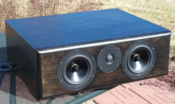
Geoff G's MTM RS150/27TDFC build thread

Collapse
This topic is closed.
X
X
 
  • Time
  • Show
Clear All
new posts
  • Geoff Gunnell
    Member
    • Nov 2006
    • 59

    #1

    Geoff G's MTM RS150/27TDFC build thread

    NOTE 8/2/18: Chris no longer publishes the series version of this crossover -- see his current crossover recommendations at:
    http://www.eldamar.net/audio/RS150MTM/

    Some interesting (IMO) cabinet building ideas remain


    Chris, I've been looking at some DIY LCR designs and your series crossover design for your RS150/27TDFC MTM intrigued me.

    AFAIK only powens who posted subsequently has built these, commenting on slightly better mids but slightly decreased bass compared to your ladder xo.
    Although he did use a 14 ga 0.09 dcr coil for L1, he said he used 18 ga Jantzens for the rest -- that would put the dcr of the other woofer-series inductor L2 at 0.48

    I had kind of put this design on the back burner until I read your recent post in the Spassvogel MT thread


    Dang that's some mighty fine phase tracking!

    So I have a few questions

    Has anyone else built/listened to these?

    Are you recommending the with Zobels or the without Zobels net?
    and perhaps related -- any simple (I know!) choices that reduce BSC?

    If you have the time to plug a 0.24 dcr in for L2, does it do anything awful (I assume not but my batting average on 'I assume' is dismal

    BTW the way I'd spec these out there's only about $33 upcharge to go from the Seas Generic ladder to the zobel'd series -- not bad at all IMO
    Last edited by theSven; 25 August 2023, 14:49 Friday. Reason: Update htguide url
  • cjd
    Ultra Senior Member
    • Dec 2004
    • 5570

    #2
    I'll take a gander later this evening or tomorrow evening (Monday is trash night, so I tend to do most of my weekly chores and am often too wiped out for much model-mucking)

    I'm not aware anyone else has built these though. I do want to, but digging in and swapping crossovers is such a pain, you know?

    C
    diVine Sound - my DIY speaker designs at diVine Audio

    Comment

    • Geoff Gunnell
      Member
      • Nov 2006
      • 59

      #3
      Thanks, Chris. No hurry -- I've read you've got a lot of projects ongoing.

      And if you do get a chance to vary L2's dcr in the series model, please take it down to 0.12 -- that and a 14 ga L1 should put total dcr in the woofer circuit at 0.21, close to the 5% of nominal Re value I've read somewhere for series xo's. A 12 ga foil coil would be another $17 over a 14 regular but might be worth it in this application.
      Last edited by Geoff Gunnell; 18 March 2008, 20:30 Tuesday.

      Comment

      • Geoff Gunnell
        Member
        • Nov 2006
        • 59

        #4
        I don't expect to be posting enough for a separate thread, but I'm going ahead with a trial build of one of the three LCRs I'll need using the series xo 'with Zobels' version of CJDs RS150 MTM.

        The L and R LCRs will sit on top of subs - SVS PB13 Ultras - that are 22" high. My semi-reclining seated ear height is 36", so I want the tweeters to be 14" up from the top of the subs. I want the speakers to be end-for-end symmetrical both for general utility and so I can swap speakers and run tweeters-out or tweeters-in, so that means a 28" tall/long cabinet with the drivers centered. With the 7.5" baffle width and 3/4" material, that means a 13 1/2" deep cabinet to achieve the 1.11 cubic foot optimal ported volume.

        The extra cabinet length outside the woofers will provide space for front porting, another requirement for me. I may go with a 3" port at one end or a 2" at each end -- haven't decided yet.

        I'll be using edge glued pine boards (I know there's a chance of the strips separating over time, but I personally have never had it happen indoors). One 6' 12" wide board will do the top, bottom, and sides, another will do the baffle and the back. 1 3/4" round handrail for braces. Barrier foam all over the inside.

        Edit 2/15: BOM slightly changed, L3 now 14ga -- only 0.09 decrease in dcr for about a $9 increase in cost.

        Edit 2/16: Parts ordered. Including wood cost of $37.95, total is now $328.28
        Gasket, glue, hookup wire and screws I already have. One can certainly build this speaker for less money -- although I did keep eyeing the red oak

        Edit 2/23: After looking things over, a few changes:
        I'm reducing inside cabinet depth from 12" to 11.25" to enable use of 1x12 oak on future speakers, and increasing baffle width to 8" to enable 3/4" barrier foam on top and bottom without blocking airflow from the RS150s. Outside length remains at 28". Gross volume 1938 cu in, 1.12 cu ft.
        The 2" Precision ports are going to be replaced by 1.5" ports. The bell of the 2" ports is a little large right next to each woofer, and the length required for 38Hz tuning is too long for the revised box depth. Since these speakers are intended for use with subs this should not be a problem.
        Instead of flush mounting the drivers I'm going to surface mount them and felt the front (and rear) of the baffle. If my Durafelt order is does not arrive Monday I may get some more incoming from Madisound.

        Edit 3/8: Mostly done, need more barrier foam to finish (Wed). A few pics so far, try to get 'em up this weekend. Notes: PE terminal cup 260-309 needs black #6 flathead screws. Adhesive back felt may shrink slightly when backing removed, add 1/16" per foot to compensate. Gold plating flakes off leads of some Dayton resistors -- next speaker I'll use these in parallel pairs, get 20W rating and doubled lead area for $2.50 @ Tried both Madisound 1/8" felt and Durafelt. Not sure if Madisound's is wool, but 'fresher' appearance and no trouble peeling off backing. Durafelt smelled like wool, on some pieces backing paper took glue with it -- still I liked it better although both were fine.

        EDIT 3/18: READ AT LEAST THROUGH POST 22 BEFORE IMITATING THIS DESIGN. Spacing barrier foam over crossover reduced interior cabinet depth 2 1/4", making correct port tuning using two 2" ports impossible (although there is a workaround). I'd recommend 703 fiberglass over the crossover unless cabinet interior depth is increased to at least 13".
        Last edited by Geoff Gunnell; 02 August 2018, 19:48 Thursday.

        Comment

        • Geoff Gunnell
          Member
          • Nov 2006
          • 59

          #5
          The first subject is mounting the Seas 27TDFC. Instead of cutting out 'ears' for the terminals I drilled two 1 1/2" holes 2 1/16" apart. Measurements shown are actual using an outside caliper.

          Click image for larger version  Name:	grg cjds mtm tdfc terminal plan.JPG Views:	1 Size:	89.7 KB ID:	863648

          Click image for larger version  Name:	grg cjds mtm tdfc terminals holes.jpg Views:	1 Size:	71.7 KB ID:	863649
          Last edited by theSven; 25 August 2023, 14:50 Friday. Reason: Update image spacing

          Comment

          • Dennis H
            Ultra Senior Member
            • Aug 2002
            • 3801

            #6
            Instead of cutting out 'ears' for the terminals I drilled two 1 1/2" holes 2 1/16" apart.
            Good one, Geoff! That's a nice clean way to do that.

            Comment

            • Geoff Gunnell
              Member
              • Nov 2006
              • 59

              #7
              Thanks for the encouragement, I certainly made several mistakes as you'll see. One was orienting the tweeter terminals horizontally. As you can see, in this baffle design placing them vertically would have made a stronger baffle.

              For a second subject, as others have said, the RS150 really needs the baffle relieved on the backside to help airflow. I am perhaps excessively paranoid about speaker attachment strength, and wanted the speaker mounting screws to have the full 3/4" baffle thickness to sink into. That limited the chamfer angle to 22.5 degrees. In the photo below you can just barely see 6 tiny pencil circles where the screws will come through right on the edge of the chamfer.

              I chose not to scallop out the sectors between the screw locations for three reasons. First, I think the 22.5 degree may be enough. Second I like to be able to rotate a driver if a screw hole becomes damaged. Third, since the drivers are flushed with felt, this is a design that can be built by folks who do not have a router -- the chamfer could be cut with the jig saw base angled.
              Click image for larger version

Name:	grg cjds mtm 22 deg chamfer.JPG
Views:	1
Size:	17.1 KB
ID:	863650
              Last edited by Geoff Gunnell; 02 August 2018, 18:45 Thursday.

              Comment

              • Geoff Gunnell
                Member
                • Nov 2006
                • 59

                #8
                I decided to felt both sides of the baffle board. Layout is easy with peel-n-stick felt, as the backing paper is easy to mark on.

                Click image for larger version

Name:	grg cjds mtm felt.JPG
Views:	1
Size:	29.7 KB
ID:	863654

                At least on the first piece you cut you'll want to add about 1/16" per foot to the overall length and width to compensate for the possibilty that the felt will contract a little bit when the backing paper is removed. The easiest way to cut the felt is one cut with a mat or xacto knife to get through the paper and glue layer, then cut the fabric with scissors -- I used curved bladed manicure scissors on the holes.

                You can see what happens if you don't allow extra length when cutting felt -- and this was in addition to the fact I had traced around the oudside of the baffle with a carpenters' pencil and cut on the line, thus adding most of another 1/16" to the cut length.

                On the frontside of the baffle, each port and driver is dropped in and the felt cut around with a mat knife, removing a ring of felt so the drivers mount to the wood.

                Click image for larger version

Name:	grg cjds mtm cutting felt.JPG
Views:	1
Size:	31.8 KB
ID:	863653

                I usually use very compressible foam weatherstripping tape for gasketing, but I really needed a zero-height solution this time, so I spread rope caulk out to an almost transparent layer with my thumb. If ease of driver removal wasn't a high priority, a thin layer of Silicon II caulk or windshield sealer would be ideal.

                Click image for larger version

Name:	grg cjds mtm rope caulk.JPG
Views:	1
Size:	51.3 KB
ID:	863659

                There won't be any baffle edge roundover/chamfer -- these will have grills. Felting both sides of the baffle definately damps baffle board resonance quite a bit. Lighting requred to get pics makes felt look ugly, actual appearance is very good IMO.

                With drivers installed, port flanges are flush with felt, drivers still a little bit proud of felt. The Durafelt I used is just a little shy of 1/8" with paper removed.
                Last edited by Geoff Gunnell; 04 August 2018, 19:56 Saturday.

                Comment

                • Xander
                  Senior Member
                  • Dec 2007
                  • 132

                  #9
                  Hmm, I've never seen felt applied to an entire baffle like that. Interesting concept. And if you'll be making grills then it doesn't really matter what it looks like so much anyway.

                  I wouldn't think the felt would dampen many resonances though...maybe prevent some reflections off the baffle, but that's about it. Unless you mean because the felt is between the driver and the baffle, so it helps decouple it some. But most people use foam or weatherstripping there anyway.

                  When you placed the baffle with the felt on it on the box in that second picture you have the baffle flipped backwards...no? Looks like the holes are chamfered to be smaller on the inside. Looks like it's right in the third pic though. Just making sure.

                  Comment

                  • cjd
                    Ultra Senior Member
                    • Dec 2004
                    • 5570

                    #10
                    The felt may help in this case because the actual baffle material is so resonant (looks like solid pine) - generally a poor choice of material for many reasons. Sometimes, you just work with what you have.

                    I felt-covered the baffles for my HT project. That was to kill reflections though, since they're behind the screen.
                    diVine Sound - my DIY speaker designs at diVine Audio

                    Comment

                    • Geoff Gunnell
                      Member
                      • Nov 2006
                      • 59

                      #11
                      It's edge glued pine -- rings like a bell undamped -- post #24 below has comments on why I chose it. I'm getting ahead of my pictures here, but I did not find the three layer 3/4" Dayton foam to be any better than 1/8" felt at damping panel resonances, although I'm sure it's great at absorbing energy inside the cabinet.

                      Xander, pic showing chamfers was backside of baffle -- I've removed it to avoid confusion.
                      Last edited by Geoff Gunnell; 04 August 2018, 21:16 Saturday.

                      Comment

                      • Hdale85
                        Ultra Senior Member
                        • Jan 2006
                        • 16120

                        #12
                        Doesn't really explain why just says that your using it.

                        Comment

                        • Geoff Gunnell
                          Member
                          • Nov 2006
                          • 59

                          #13
                          Let's just say curiosity at this point ;^).

                          I can say that the red oak I'm considering is a lot less resonant than the pine.

                          I can also say that both HDepot and Lows intermittantly stock 1" thick edge glued pine in 2' x 4' only -- I've got several sheets and it's a LOT less resonant than the 3/4".

                          Interior bracing, panel dampening, relative expense and ease of manufacture are all tradeoffs -- I'm expecting more barrier foam Wednesday and that'll finish them up enough to listen to . . .
                          Last edited by Geoff Gunnell; 04 August 2018, 21:15 Saturday.

                          Comment

                          • Geoff Gunnell
                            Member
                            • Nov 2006
                            • 59

                            #14
                            The box:

                            The PE barrier foam will not stay attached when inverted, figure on gluing it in. Still, the peel off backing paper is great to mark layout on.

                            Click image for larger version

Name:	grg cjds mtm PL foam.JPG
Views:	1
Size:	43.5 KB
ID:	863655

                            A couple hints on polyurethane in a caulking tube:
                            Cut the samllest hole you can, right below the tip, not only so you can seal it with a 16d nail, but because . . .
                            This stuff expands in the tube. Half the length of one of the gluelines above came out after I hit the pressure release -- I wasn't heating the tube with my hand -- this in a 63 degree basement. Have paper towels handy

                            Right now the box has only one 1x4 center brace:

                            Click image for larger version

Name:	grg cjds mtm foam.JPG
Views:	1
Size:	81.5 KB
ID:	863656

                            Oddly enough, knuckle-rapping indicates little need for additional braces except along the edges where the baffle and back will attach.

                            The crossover is glued to the inside back wall:

                            Click image for larger version

Name:	grg cjds mtm series crossover.JPG
Views:	1
Size:	77.7 KB
ID:	863657

                            The only reason I used a terminal cup was I thought I might end up close to the wall with the rear surrounds -- that's changed, so I'll use posts from now on. Green wire is 14ga, speaker wire is 16ga with soldered on disconnects.

                            Finishing up using nothing but PE 3/4" barrier foam involved keeping the foam away from the resistors in the crossover network. So I bridged across the xo with a center support on the center coil. Pressure pulses from the ports will hit the 'solid' piers at each end. Hopefully reduction of interior volume will still allow workable port area/length solution -- we'll see.

                            Click image for larger version

Name:	grg cjds mtm foam over crossover.JPG
Views:	1
Size:	20.9 KB
ID:	863658

                            Wrapping the port tubing with duct tape slightly reduces sound produced when tube is tapped with your finger, and two layers were an audible improvement over one layer. How audible this is I don't know but it's cheap and easy to do. Y'all knew I was going to use audio tape somewhere in this project, didn't you? :}

                            Click image for larger version

Name:	grg cjds mtm port taped.JPG
Views:	1
Size:	74.3 KB
ID:	863660
                            Last edited by Geoff Gunnell; 04 August 2018, 19:53 Saturday.

                            Comment

                            • Geoff Gunnell
                              Member
                              • Nov 2006
                              • 59

                              #15
                              Thanks for the separate thread, Thomas -- it kinda grew on me.

                              Well, it's 'finished' and playing in the center channel position. I'd take a pic but since Zaph said he'd take his web site down if he ever saw any DIYer do this, we can't have that! Just the usual poor center-on-shelves-below-TV placement.

                              Anyway we've played a few hours of TV news, movies, and music. The music was Corinne Bailey Rae, a good mix of bass, vocal, and treble. A Yamaha 3800 feeds a Rotel 1095.

                              First the midrange -- very, very nice, subjectively low distortion. Connie's voice is all I remember

                              Treble is a little hot to my taste 8k+. I set one of the Yamaha's parametrics at 8k, might use another centered a little higher. My guess is I'll end up with the inverse of the treble plateau of the 27TDFC, so if I build more of these I'll probably use Chris's dedicated 27TDFC net. I've always been pickier than most about my tweeters tho.

                              Bass still needs work. I've possibly overdamped the cabinet by lining it with PE 3/4" barrier foam, and I've certainly reduced the effective volume. Right now the best tuning is only one 2" port open. Still, set as the only Large speaker with all bass directed to it, the speaker aquitted itself well, but crossing to subs at 80Hz was definately better.

                              Crossed to a sub at 80 Hz and with a treble roll off above 8kHz, this speaker diappeared into the soundstage as well as any center I've tried, and I'm eagerly awaiting more music time!

                              My goals were to improve on the off-axis dispersion of my current MTM's which use the Vifa XT25, while fitting into limited space, and this speaker certainly does that. I made several mistakes along the way which I'll talk about after a good night's sleep!

                              Comment

                              • ThomasW
                                Ultra Senior Member
                                • Aug 2000
                                • 10980

                                #16
                                Originally posted by Geoff Gunnell
                                I'd take a pic but since Zaph said he'd take his web site down if he ever saw any DIYer do this, we can't have that!
                                Knowing Zaph that statement was no doubt sarcasm. So let's see a few pics of the assembled speaker.... :T

                                IB subwoofer FAQ page


                                "Complicated equipment and light reflectors and various other items of hardware are enough, to my mind, to prevent the birdie from coming out." ...... Henri Cartier-Bresson

                                Comment

                                • cjd
                                  Ultra Senior Member
                                  • Dec 2004
                                  • 5570

                                  #17
                                  I think Zaph was only talking about his own designs, too.

                                  How did you calculate the port tuning?

                                  C
                                  diVine Sound - my DIY speaker designs at diVine Audio

                                  Comment

                                  • Geoff Gunnell
                                    Member
                                    • Nov 2006
                                    • 59

                                    #18
                                    Sorry about the quality of these pics. Here's one of the speaker:

                                    Click image for larger version

Name:	grg cjds mtm finished.JPG
Views:	1
Size:	87.2 KB
ID:	863661

                                    And the placement:

                                    Click image for larger version

Name:	grg cjds mtm placement.JPG
Views:	1
Size:	36.6 KB
ID:	863662

                                    Chris, I haven't re-calculated the porting since initial design (I use Precision Port's online calculator) but it was always close even with my initial planned 12" inside cabinet depth -- close in fitting in adequate port length with 2 2" ports. I could have still come close using 11 1/4" inside depth (allowing construction with 1x12 stock) by eliminating the inside port flare, but not only did the PE 3/4" barrier foam on the cabinet sides (I have to say in my opinion here) reduce the effective cabinet volume, but the construction I had to use to keep the foam a fire-safe distance away from the crossover components reduced cabinet inside depth another 2 1/4". Although switching to a thin barrier layer adhered directly to the inside of the cabinet for panel dampening, then 1" 703 fiberglass over that, would perhaps work better in this space-limited application, the main 'fix' is to simply go to a larger cabinet to start with -- simple to do as both front and rear panels are merely screwed/felt gasketed on.

                                    Why I chose to try the original 2" ports over 'Zaph's favorite' 1 1/2s, and what I'm going to do next, will have to wait for another day -- right now, other than rolling off the tweeter as I said, I'm not having a problem with the bass -- I just redirected all bass to the center and then played De Phazz Godsdog track 4 'Steps Ahead' -- if there was port noise from the one 2" port I was unable to hear it at the two meter closest distance I felt comfortable approaching at the volume I was playing
                                    Last edited by Geoff Gunnell; 04 August 2018, 20:14 Saturday.

                                    Comment

                                    • Geoff Gunnell
                                      Member
                                      • Nov 2006
                                      • 59

                                      #19
                                      Port choices:

                                      After changing my design to accommodate construction from 1x12 stock, I realized that I might run out of cabinet depth for 2" ports, so I ordered some 1 1/2" ports from PE:


                                      Click image for larger version

Name:	grg cjds mtm 1 1-2 ports.JPG
Views:	1
Size:	81.1 KB
ID:	863663

                                      The idea of butting two up end-to-end to make a longer port with an inside flare sounded good:

                                      Click image for larger version

Name:	grg cjds mtm ports butted.JPG
Views:	1
Size:	26.2 KB
ID:	863664

                                      But the more I looked at it, the more I wished for a coupling ring or some other way to strengthen the joint -- it's some pretty thin wall tubing to butt joint. Of course solvent bonds are strong and it probably would have been fine -- but then I started to get a little concerned about the unsupported length with the mass of the inside flare on the end, and concluded I'd really like an inside port support, something I was trying to avoid. Had I intended to use the inside flare on the 2" Precision port I would have used an inside brace there also.

                                      So I cut the baffle for the 2" Precision ports -- and later ended up loosing 2 1/4" of cabinet depth using foam barrier dampening over the rear mounted crossover.

                                      But I did come up with a solution -- it just so happens that 1 1/4" PVC pipe female couplings (white), and 1 1/4" plastic electrical conduit couplings (grey):

                                      Click image for larger version

Name:	grg cjds mtm port bushings.JPG
Views:	1
Size:	53.8 KB
ID:	863665

                                      are almost an exact fit inside the Precision Port 2" tubing:

                                      Click image for larger version

Name:	grg cjds mtm port bushing installed.JPG
Views:	1
Size:	54.0 KB
ID:	863666

                                      The electrical conduit coupling is a tighter fit -- either would need to be glued in, but will stay in place unglued for trial and error tuning. Three or four of these in each port converts the ports to 1 5/8" ID. Of course taking a rat tail file or cutter head on a flexible shaft and knocking down the barrier rings in the center of each coupling would be necessary, as would chamfering the leading edge of the front coupling and the trailing edge of the rear coupling.

                                      Next I'm going to try replacing the barrier foam with 703 fiberglass, starting with the back wall over the crossover (exactly where I wanted to use barrier foam the most). Next would be to increase cabinet inside depth from 11.25" to at least 13.25". If I exceed 15" overall depth in the surround locations I'll have to spend another $120 on different wall mounts . . .
                                      Last edited by Geoff Gunnell; 04 August 2018, 20:53 Saturday.

                                      Comment

                                      • ThomasW
                                        Ultra Senior Member
                                        • Aug 2000
                                        • 10980

                                        #20
                                        Image not available

                                        Use of this adapter has makes the flare basically worthless. The idea is to have a totally smooth transition between the tube and the exit.
                                        Last edited by theSven; 25 August 2023, 14:50 Friday. Reason: Remove broken image link

                                        IB subwoofer FAQ page


                                        "Complicated equipment and light reflectors and various other items of hardware are enough, to my mind, to prevent the birdie from coming out." ...... Henri Cartier-Bresson

                                        Comment

                                        • Dennis H
                                          Ultra Senior Member
                                          • Aug 2002
                                          • 3801

                                          #21
                                          Originally posted by ThomasW
                                          Use of this adapter has makes the flare basically worthless. The idea is to have a totally smooth transition between the tube and the exit.
                                          Yeah, it's supposed to be smooth all the way through the pipe. If you're worried about the strength of a butt joint, you can reinforce it with some epoxy and some cloth (old jeans, whatever) wrapped around the outside.

                                          Comment

                                          • Geoff Gunnell
                                            Member
                                            • Nov 2006
                                            • 59

                                            #22
                                            I agree with both your comments. With respect to the 1 1/2" port tubes, I had also considered reenforcing the butt-joined tubes with a wrap of fiberglass cloth / gelcoat or something similar, but I still would have need to add (IMO) a support brace for the inner end of the tubing -- that's just me eyeballing the length of the tube, the mass of the inner flare at the unsupported end, and the relatively small flange mounting.

                                            Let's get this over with and say I screwed up. Chris used a 3" port in his design, close to 2 2" ports, and my initial gross volume of 1.2 cu.ft. was in line with this.
                                            However, I lost cabinet depth and volume along the way, and 2 2" ports are overkill for the enclosure as constructed.

                                            Had I thought a little more I might have correlated some other data:

                                            Both the Dali Vokal 2 (which I own) and ACI's XLC center, both 5.x" woofer WTMWs, use dual 1" (or close to that) small radius flare ports -- and I've never heard or read of port noise issues with either.

                                            Closer to home, Jon's Modula MTM with two RS180's uses one 2" port -- haven't heard of port noise issues there either.

                                            Anyway, about 10 minutes with a rat tail file and a rotary rasp in a hand drill produces this:

                                            Click image for larger version

Name:	grg cjds mtm port bushing contoured.JPG
Views:	1
Size:	32.8 KB
ID:	863667Click image for larger version

Name:	grg cjds mtm contoured port bushing installed.JPG
Views:	1
Size:	24.5 KB
ID:	863668

                                            which I'll taper further, sand smooth etc. -- this just shows the concept ;}

                                            Based on what I've learned building this center speaker, when I build the L and R speakers I'll do some things differently:
                                            1. Orient tweeter terminal cutouts vertically
                                            2. Use one 2" port (forget symmetry for center, will be covered with grill anyway) or two 1 1/2" or similar ports -- the only longer ones I know of are PE's adjustable ones.
                                            3. Try another one of Chris's crossovers, either the Seas generic or 27TDFC
                                            4. Replace barrier foam with vinyl dampening layer topped with 703. I'd really like to find some combination that gets my total cost under $5 @ sq ft.
                                            5. If that doesn't work, or maybe even if it does, increase cab depth.

                                            Realize that I'm perfectly happy with the speaker as it is now -- it has permanently replaced what I was using before, primarily due to more even power radiation over a wider angle both horizontally and vertically. But I can do better . . .

                                            Also, it's high time I said Thank You! to you Chris for a good design!
                                            Last edited by Geoff Gunnell; 04 August 2018, 21:10 Saturday.

                                            Comment

                                            • JonP
                                              Senior Member
                                              • Apr 2006
                                              • 692

                                              #23
                                              Originally posted by Geoff Gunnell
                                              For a second subject, as others have said, the RS150 really needs the baffle relieved on the backside to help airflow. I am perhaps excessively paranoid about speaker attachment strength, and wanted the speaker mounting screws to have the full 3/4" baffle thickness to sink into. That limited the chamfer angle to 22.5 degrees.

                                              I chose not to scallop out the sectors between the screw locations for three reasons. First, I think the 22.5 degree may be enough. Second I like to be able to rotate a driver if a screw hole becomes damaged. Third, since the drivers are flushed with felt, this is a design that can be built by folks who do not have a router -- the chamfer could be cut with the jig saw base angled.
                                              A thought on this for next time... I always try for a 45 deg chamfer, (bought the router bit deep enough for 3/4") and I know what you mean. I did this with a Modula MT and a RS180, with just screws and felt comfortable, but it was Baltic Birch.

                                              I also did this with a HiVi B3N, which REALLY needs back chamfering, and has a REALLY narrow screw placement. My solution was to make little triangular wedges of BB, and epoxy them on at the screw points. Then there's a small area chunk of depth for the screws to utilize. You could knock/cut them off, and glue new ones on, if you needed to rotate a driver like you said.

                                              I made the B3N chamfers with a jig saw, BTW... that project was predating my bit purchace. A little rough, but not bad...

                                              Comment

                                              • Geoff Gunnell
                                                Member
                                                • Nov 2006
                                                • 59

                                                #24
                                                Thanks, Jon. Although I didn't start planning with this as a goal, as I went along I got the idea of a speaker design that could be built with just a jig saw and drill. That's all I had years ago, and although I'm blessed with niceties like a table saw and a sliding miter saw now, as we get older and downsize our living quarters I forsee the day coming when I don't have the space for bench tools.
                                                I'd definately recommend anyone intending to use a jig saw for all their cutting get one with blade stabilization like the Bosch 1590.

                                                I never completely answered Dougies earlier question about why I chose the edge-glued pine boards. Part of the reason was limited space around my table saw -- right now infeed/outfeed space limits me to ripping 6' material. Part was convenience, since (originally) the cabinet inside depth was 12', meaning I didn't have to rip anything except the front and back. Part was the fact I personally have never had the planks separate, although I've certainly seen them that way in the store -- I closely examine each piece before I buy, and I've returned a couple over the years.

                                                And part was the fact that the thin ply 3/4" plywood I looked at wasn't enough better sonically for enclosure panels this small. Based on knuckle rapping, I'll need the same amount of cross bracing either way -- and I'll need an adhered panel deadening layer either way. This time, even if I use PE's barrier foam again, I'm going to start by gluing soft vinyl peel-n-stick tile directly to the wood -- I've already tried a test piece and it dampens the panel resonances significantly for about $1 @ sq ft. My one concern was that the tile wear surface might be too slick to glue foam to, but polyurethane glue sticks like . . . glue

                                                I considered Whispermat 1 from SilentSource for this, but I'll probably stay with the PE foams. The 18x24 stock size they use and the high cost have forced me to re-design enclosure dimensions around low-waste cutting patterns for the foam, something I missed the first time around.
                                                Those interested in using one of the Hushfoam/Hushcloth type foam products
                                                like WM and PE might find this link interesting:

                                                I have no idea how accurate/applicable these numbers are but they're the only NRC's (as oppose to transmission loss) I've seen for this type product.

                                                Comment

                                                • Geoff Gunnell
                                                  Member
                                                  • Nov 2006
                                                  • 59

                                                  #25
                                                  I've been putting off posting until I could get a scanner hooked up to post drawings of the new cabinet design, but there's been a change of plan .

                                                  My wife told me she didn't have anything for my birthday yet, and asked if there was anything I needed for my speaker project. Long story short, I'm shifting this project over to RS180-27TDFC Modula MTMs -- and the parts have been ordered!

                                                  The cabinets will be very similar to the ones in this thread except larger --drivers surface mounted and the baffle covered with felt. Inside, various grades of PE foam will be applied to a panel dampening layer of soft vinyl tile -- and this time the crossover will have it's own enclosed space. Since most of the build will be the same, I'll just add some finished pics here when I'm done.

                                                  EDIT 8/4/18: I just finished a long overdue refresh of this thread, moving a few things around for clarity and restoring the images.
                                                  The Modulas never got built. The speaker described in this thread is still my center channel speaker, and I have no plans to change it!
                                                  Last edited by Geoff Gunnell; 04 August 2018, 21:32 Saturday.

                                                  Comment

                                                  • technimac
                                                    Senior Member
                                                    • Feb 2005
                                                    • 233

                                                    #26
                                                    Originally posted by Geoff Gunnell
                                                    ...This stuff expands in the tube. Half the length of one of the gluelines above came out after I hit the pressure release -- I wasn't heating the tube with my hand -- this in a 63 degree basement. Have paper towels handy ....
                                                    Geoff,
                                                    I've used a lot of PL Poly and that problem is common.
                                                    It's caused by a "bubble" of air that's trapped in the tube when it's filled at the factory, not by the glue itself.
                                                    Liquid under pressure doesn't contract or expand, but air does.
                                                    So when you're using a new cartridge of this, or any glue, that "air pocket" compresses, stores up the pressure and gradually releases it - even after you've hit the pressure release.
                                                    At some point in its life, the tube will expel the "bubble" in a lengthy "fart". 8O
                                                    Following this, there will be no more "post-trigger" seepage because only liquid glue is left in the cartridge.
                                                    It's a PITA, but once you know what to expect, it's possible to quit "on the trigger" a little early and just let the "bubble pressure" complete the job.
                                                    To reduce this problem, I store a new cartridge upright on its "butt end" to encourage the bubble to migrate to the "tube tip" end, meaninig that the bubble is expelled early in the life of the cartridge. :B
                                                    As for cleanup, paint remover/thinner and disposable rubber/plastic gloves are always part of my equipment list when using Polyurethane glue. :W
                                                    HTH, Bruce
                                                    "While we're at it" - the four most dangerous words in Home Improvement

                                                    Comment

                                                    • Geoff Gunnell
                                                      Member
                                                      • Nov 2006
                                                      • 59

                                                      #27
                                                      All good ideas, Bruce.

                                                      Frankly, I've experienced some 'after-squirt' both before and after 'tube-fart' :B
                                                      with all the glues/caulks I've used -- the PL poly just seems to be more like the Energizer bunny, it keeps going and going and going . . .

                                                      This is my first time using a polyurethane glue for other than very small repairs, and it certainly works well for many aspects of speaker building. It has good tack to most surfaces, is thin enough to spread, allows resonable working time to position parts unlike contact cement, and although as you say gloves are a good idea, I personally feel comfortable working with it barehanded (unlike, say, the cyanoacrilates) risking occasional brief skin contact, provided I don't let it dry on my skin. This should in no way be taken as recommendation that anyone not explicitly follow the safety labeling on the product, merely as the inane ramblings of an old man who still uses a damp finger to smooth PolySeamSeal into trim cracks. And this from someone who won't saw MDF, won't use many high VOC products, and thinks spray adhesives should not be for sale to the general public. :E

                                                      Comment

                                                      Related Topics

                                                      Collapse

                                                      • moab_dan
                                                        rs150 mtm for 20x20 HT room, good idea?
                                                        by moab_dan
                                                        I am trying to figure out what will work best for my HT room.
                                                        I have been looking at the CJD RS150 mtm.
                                                        I like his design because I have enough room below the screen to stand the center channel upright.
                                                        The modula rs180 mtm is outside my budget due to the x-over.
                                                        I have several...
                                                        25 March 2009, 16:47 Wednesday
                                                      • mischmat
                                                        RS150MT w/ 27TDFC
                                                        by mischmat
                                                        Changed my mind on selling the tweeters once I started looking into surrounds again. NatP's are in progress and I'm thinking of building the RS150MT with the Seas option for surround duty. I believe Post 59 here is the parts list but, I can't seem to find a schematic anywhere or my search skills need...
                                                        01 May 2015, 12:49 Friday
                                                      • catacon
                                                        CJD RS150 Center Project
                                                        by catacon
                                                        Hey everybody,
                                                        I've been looking for a center channel that will match my RS180 Modula MTs and MTMs. Well it seems that Chris' RS150/27TDFC center channel fits the bill. It will be a little while before I build, but I thought I would start early with my questions.

                                                        1) In this schematic...
                                                        11 June 2008, 20:56 Wednesday
                                                      • eddo
                                                        RS150 MTM build
                                                        by eddo
                                                        Thought I'd post a couple of images of the RS150S-8/27TDFC MTMs that I just built. Many thanks to CJD for posting his design. I don't have the time or resources for testing and designing at the moment, so its always appreciated when others are willing to share designs.

                                                        First, some info...
                                                        25 April 2008, 13:47 Friday
                                                      • Undefinition
                                                        Is there interest in an RS150 dipole?
                                                        by Undefinition
                                                        I'll let you all in on a little secret... I have been planning another entry into the MTMW open-baffle catalog.

                                                        Not that I really need to. But I think that some people might have been a bit incredulous of the Sunflowers; that there was an expectation that if someone did an dipole or OB...
                                                        09 March 2009, 21:50 Monday
                                                      • Loading...
                                                      • No more items.
                                                      Working...
                                                        Searching...Please wait.
                                                        An unexpected error was returned: 'Your submission could not be processed because you have logged in since the previous page was loaded.

                                                        Please push the back button and reload the previous window.'
                                                        An unexpected error was returned: 'Your submission could not be processed because the token has expired.

                                                        Please push the back button and reload the previous window.'
                                                        An internal error has occurred and the module cannot be displayed.
                                                        There are no results that meet this criteria.
                                                        Search Result for "|||"