VituixCAD v2

Collapse
X
 
  • Time
  • Show
Clear All
new posts

  • Nil L
    replied
    Remove the dependence of the resistance of the inductor on the value of the inductance? The resistance of the inductor too much influences the fitting of the elements to obtain the best frequency response and phase. This would be a backward movement. I didn't use the option to set max and min for DCR, but this is a ok solution. Thank you.

    Leave a comment:


  • kimmosto
    replied
    Originally posted by Nil L
    When the optimizer or user changes the value of the inductor back and forth for a long time, it eventually turns out that the resistance of the inductor has become unrealistic
    Optimizer does not change DCR by default. Optimizer can change it, but not before you have checked Opt cell manually.
    You can lock DCR between Min and Max to avoid exceeding possible range. This is one cure also to drifting due to rounding. Unfortunately calculation has to be relative because different coil cores have totally different DCR range with the same L and wire gauge. Calculation remains as is, but I will remove whole feature if too much complains. Personally I don't like or need it.
    Click image for larger version  Name:	image.png Views:	0 Size:	4.4 KB ID:	937480

    Leave a comment:


  • Nil L
    replied
    Originally posted by kimmosto

    That gives smaller error with target given by user, and target does include level. Or max gain constraint is checked while target includes requirement to extend bass range. Several possible reasons.
    Try to limit number of optimized parameters to increase your own control to optimizing process and awareness what the consequences could could be if optimized parameters affect outsize target's range.
    I played around with 'seek level' and 'weight' and got a decent result. Thanks for the advice.

    When the optimizer or user changes the value of the inductor back and forth for a long time, it eventually turns out that the resistance of the inductor has become unrealistic, for example, 1.2 mH has become 9 ohms. If this is due to the accumulation of rounding errors, is it possible to add a check to ensure that the obtained value of the inductance and wire thickness correspond to the standard resistance value for them?

    Leave a comment:


  • kimmosto
    replied
    Purifi Audio drivers added to online database

    PTT10.0X04-NAB-02
    PTT4.0M04-NAC-03
    PTT4.0M04-NAC-04
    PTT4.0M04-NFC-01
    PTT4.0M04-NLC-02
    PTT4.0M08-NAC-03
    PTT4.0M08-NAC-04
    PTT4.0M08-NFC-01
    PTT4.0M08-NLC-02
    PTT4.0PR-NA2-02
    PTT4.0PR-NF2-01
    PTT4.0PR-NL2-01
    PTT4.0X04-NAC-03
    PTT4.0X04-NAC-04
    PTT4.0X04-NFC-01
    PTT4.0X04-NLC-02
    PTT4.0X08-NAC-03
    PTT4.0X08-NAC-04
    PTT4.0X08-NFC-01
    PTT4.0X08-NLC-02
    PTT5.25M04-NFA-02
    PTT5.25PR-NF2-01
    PTT5.25X04-NFA-01
    PTT5.25X04-NFA-02
    PTT5.25X08-NFA-01
    PTT5.25X08-NFA-02
    PTT6.5M04-NFA-01
    PTT6.5M04-NLA-02
    PTT6.5M08-NAA-07
    PTT6.5M08-NAA-08
    PTT6.5M08-NFA-01
    PTT6.5M08-NLA-02
    PTT6.5PR-NA2-03
    PTT6.5PR-NF1-01
    PTT6.5PR-NL1-01
    PTT6.5W04-NFA-01
    PTT6.5W04-NLA-10
    PTT6.5W08-NAA-07
    PTT6.5W08-NAA-08
    PTT6.5W08-NFA-01
    PTT6.5W08-NLA-10
    PTT6.5X04-NAA-07
    PTT6.5X04-NAA-08
    PTT6.5X04-NFA-01
    PTT6.5X04-NLA-10
    PTT6.5X04-NLB-02
    PTT6.5X08-NAA-07
    PTT6.5X08-NAA-08
    PTT6.5X08-NFA-01
    PTT6.5X08-NLA-10
    PTT6.5X08-NLB-02
    PTT8.0PR-NA2-01
    PTT8.0X04-NAB-02
    PTT8.0X08-NAB-02

    Leave a comment:


  • kimmosto
    replied
    2.0.106.1 (2023-05-18)

    Main
    • Blue color in rainbow palette changed to lighter (RGB=80,80,255) to be more visible in dark mode as line chart.
    • Curve legends of exported/copied Directivity charts are not sorted aphabetically to maintain correct angle order.
    This more official release. 80,80 does not change much compared to 76,76. It's just average of 64 and 96, and divisible by 16. Nerd numbering...

    Leave a comment:


  • Reet
    replied
    It's a bit better, thank you. At least for symmetrical cabinets, I can always select negative angles to use red and green for the more interesting traces for even greater visibility.

    Leave a comment:


  • kimmosto
    replied
    2.0.106.1 has blue=76,76,255. I can tune it more if needed.

    Leave a comment:


  • kimmosto
    replied
    I'm trying to find setting which would be the same and okay for both modes and all chart types. For example Blue=76,76,255 doesn't look too lame as waterfall
    Click image for larger version

Name:	image.png
Views:	909
Size:	202.2 KB
ID:	936788

    Click image for larger version

Name:	image.png
Views:	916
Size:	186.9 KB
ID:	936789

    Leave a comment:


  • Reet
    replied
    64 or 96 options are my preference, probably 96,96,255 is best. All are an improvement to visibility.

    Leave a comment:


  • kimmosto
    replied
    This is Blue=96,96,255 with 1px line width
    Click image for larger version

Name:	image.png
Views:	901
Size:	213.0 KB
ID:	936785

    Leave a comment:


  • kimmosto
    replied
    What is the best?

    Blue=0,0,255:
    Click image for larger version

Name:	image.png
Views:	940
Size:	227.8 KB
ID:	936780
    Blue=64,64,255:
    Click image for larger version

Name:	image.png
Views:	940
Size:	241.5 KB
ID:	936781
    Blue=96,96,255:
    Click image for larger version

Name:	image.png
Views:	917
Size:	243.6 KB
ID:	936782
    Blue=128,128,255:
    Click image for larger version

Name:	image.png
Views:	932
Size:	244.1 KB
ID:	936783

    Lighter blue might work also in normal mode.
    Sorting of legends does not look good with Directivity Line charts I haven't noticed that before because I don't look directivity as line chart.

    Leave a comment:


  • Reet
    replied
    Is there any chance of lightening a few of the lines for the directivity line chart in dark mode? The dark blue lines on black background are quite hard to make out.

    Click image for larger version

Name:	image.png
Views:	931
Size:	183.8 KB
ID:	936778

    Leave a comment:


  • Reet
    replied
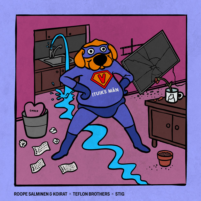
    Not really my taste of music, but I enjoyed the artwork. It's too bad they didn't use and X in his name to make him cooler

    Leave a comment:


  • kimmosto
    replied
    Polite translation of previous. Replace "the Goofy Guy" with "F*ck up Man" to get more honest version.
    https://lyricstranslate.com/en/vitui...goofy-guy.html

    Leave a comment:


  • kimmosto
    replied

    Leave a comment:


  • kimmosto
    replied
    Originally posted by Nil L
    Sometimes the VituixCad optimizer decides to lower the overall level. Sometimes very strong, by 20-30 dB. What reasons can lead to such behavior?
    That gives smaller error with target given by user, and target does include level. Or max gain constraint is checked while target includes requirement to extend bass range. Several possible reasons.
    Try to limit number of optimized parameters to increase your own control to optimizing process and awareness what the consequences could could be if optimized parameters affect outsize target's range.

    Leave a comment:


  • kimmosto
    replied
    2.0.106.0 (2023-05-14)

    Main
    • Rotation R and Tilt T parameters added to Driver offset group in Room tab.
    • Planes rotation range in Driver offset group extended back to ±90 deg.
    • Eg, Tg and Rg changed back to global variables to allow changes in Driver offset group without jumping back to default values. Bug since 2.0.104.0 (2023-05-02).

    Leave a comment:


  • Nil L
    replied
    Sometimes the VituixCad optimizer decides to lower the overall level. Sometimes very strong, by 20-30 dB. What reasons can lead to such behavior?

    Leave a comment:


  • kimmosto
    replied
    Originally posted by Quza
    Also, send me a message here if you want another hint regarding the DAC you asked about.
    DAC deal went to local dealer. Antti will ask directly from sales dep. are they willing to sell two or just one for the lowest price. I guess he could pay a bit more if the lowest offer was primarily personal. Thanks anyway!

    Leave a comment:


  • Quza
    replied
    Originally posted by kimmosto
    2.0.105.0 (2023-05-04)Main
    • Added t.amp 48k to DSP system list in Options. Plays t.amp Quadro 500 DSP at the moment.
    I'll test the 4x4 later today and the 204/206/408 series tomorrow. Also, send me a message here if you want another hint regarding the DAC you asked about.

    Leave a comment:


  • kimmosto
    replied
    2.0.105.1 (2023-05-08)

    Enclosure
    • Driver database can also be XML file with either .vxd or .xml extension.

    Leave a comment:


  • kimmosto
    replied
    2.0.105.0 (2023-05-04)

    Main
    • Added t.amp 48k to DSP system list in Options. Plays t.amp Quadro 500 DSP at the moment.

    Leave a comment:


  • JonMarsh
    commented on 's reply
    This was an interesting change for which I enjoy the added control.

  • kimmosto
    replied
    2.0.104.1 (2023-05-03)
    * Impulse response window did not export anything due to modified filename extension filters. Bug since 2.0.101.5 (2023-04-21)

    Leave a comment:


  • kimmosto
    replied
    2.0.104.0 (2023-05-02)

    Main
    • Added t.racks 48k and t.racks 96k to DSP system list in Options. t.racks 48k should be okay for t.amp Quadro 500 DSP too.
    • Added Tg[us] parameter to Generator component for time shifting of all acoustical responses.
    • Smoothing of all drivers can be adjusted at once by pressing Alt-key while selecting from the list box.
    Merger
    • Minimum transition frequency dropped from 40 to 20 Hz.

    Leave a comment:


  • kimmosto
    replied
    Aspect ration setting is still in Options due to global effect.

    2.0.103.2 (2023-04-27)
    • Aspect ratio control in Options window changed from text box to list box including Full, 4:3, 3:2, 16:9 and 10-50 dB/dec.
    ​That looks too good and simple to be whole truth. Function is actually quite complex. From user manual:

    Click image for larger version

Name:	image.png
Views:	1079
Size:	30.1 KB
ID:	933516

    Leave a comment:


  • Reet
    replied
    Originally posted by kimmosto
    Checkbox for switching between 16:9 and IEC 60263 can be added later, but I don't know yet where it should be.
    Thank you. My thought would be either aspect ratio selection via right click context menu, or along top bar with adjustment buttons for horizontal and vertical scale.

    Leave a comment:


  • kimmosto
    replied
    Originally posted by Reet
    It would be helpful is this were an easily select-able option.
    Feature is now fixed while chart is zoomed in if unit of left Y scale is dB. Checkbox for switching between 16:9 and IEC 60263 can be added later, but I don't know yet where it should be.

    2.0.103.1 (2023-04-25)

    Main
    • Zoomed view of charts with left Y axis in dB follow aspect ratio setting in Options window.
    Known weakness of this standard is that limiting frequency does not provide any more resolution without limiting also Y axis. Just narrow graph looking stupid.
    Click image for larger version

Name:	image.png
Views:	309
Size:	22.2 KB
ID:	933506

    Leave a comment:


  • JonMarsh
    replied
    OK, that's a better way to work around this than what I've been doing opening up components, and it's kind of obvious what the intent is from the schematic representation. Thanks for the suggestion! I'm going to try implementing it in a few current projects!

    Leave a comment:


  • kimmosto
    replied
    Originally posted by JonMarsh
    ... a few chuckles...
    I can essentially simulate this by having a component such as a resistor which I enable the "open" function
    You're not the first one asking switch... I'd like to suggest using short wires. It's not far from switch symbol, and wire groups with part ID as a comment can be added to component library by anyone, any capacity and any orientation.
    Click image for larger version

Name:	image.png
Views:	312
Size:	11.7 KB
ID:	933502
    Equation parser understands some logic functions too, but I have not tested is it possible to use e.g. integer parameter for switching R between 1 GOhms and 1 uOhms. Open/not can't be controlled with expression field so library blocks using equations can play with resistors and resistance only.

    Leave a comment:


  • theSven
    commented on 's reply
    Were these gifs or jpegs? They are not coming up at all. Do you have the images still that you could share with me? I would recommend only using JPEG, not GIFs they don't play well. The attachments should be attached to this post, but none of them are on the post.

  • JonMarsh
    replied
    OK, this request should be good for a few chuckles...

    Near as I can see, there is no component element that is simply a switch, to open or close to set a connection state.

    Yes, I can essentially simulate this by having a component such as a resistor which I enable the "open" function on or not, or do this with existing parts in the "signal path", but for the purpose of creating some types of user adjustable crossover configurations and documenting it clearly within VitiuixCAD itself and having that schematic have clear intent for others, I would find this rather handy....

    Low tech, but quite useful for me, especially for some new designs underway intended to have some flexibility for room positioning. Maybe for others? Just a SPST switch would be fine, (that's what I'm using physically) though I can imagine a SPDT switch covering more applications.


    Leave a comment:


  • kimmosto
    replied
    Originally posted by Quza
    Exported as .csv with 5000 data points for SPL and phase: https://nx8218.your-storageshare.de/s/awaq9pkFXNTRNwn
    Text in changelog meant impulse response files​. Your example is some strange frequency response file which won't be supported.

    Leave a comment:


  • Quza
    replied
    Originally posted by kimmosto
    2.0.101.1 (2023-04-03)Convert IR to FR
    • Added support for WAV and TXT impulse response files exported from Audio Precision.
    Does this work with repeat measurements, too?
    I used to export 19 measurements every 10° as single .csv with a fixed amount of data points for SPL and phase, which then could be split into individual files for VituixCAD with this python script:
    Code:
    #ChatGPT says this isn't elegant, and it's right.
    import sys, csv
    
    try:
        droppedFile = sys.argv[1]
    except IndexError:
        print("No file dropped!!!")
    
    start = 0
    stop = "20000"
    string = "RMS Level"
    
    orientation = input("HOR, VER-, VER+?")
    
    with open(droppedFile, 'r') as measurement_file:
        reader = csv.reader(measurement_file, delimiter=';')
        measurement_data = list(reader)
    
        for i, v in enumerate(measurement_data):
            if "Phase" in measurement_data[i]:
                print("Phase starts at: " + str(i))
                break
    
        for rowampl, item in enumerate(measurement_data):
            if rowampl > i:
                print("should be done")
                print(str(rowampl) + ">" + str(i))
                break
            if string in measurement_data[rowampl]:
                print(str(start) + "0°")
                fout = open("" + orientation + str(start) + "0.txt", "w")
                rowphase = rowampl + i
                start += 1
                try:
                    while stop not in item[0]:
                        ampl = measurement_data[rowampl]
                        phase = measurement_data[rowphase]
                        fout.write(ampl[0] + ";" + ampl[1] + ";" + phase[1] + "\n")
                        rowampl += 1
                        item = measurement_data[rowampl]
                        rowphase = rowampl + i
                    ampl = measurement_data[rowampl]
                    phase = measurement_data[rowphase]
                    fout.write(ampl[0] + ";" + ampl[1] + ";" + phase[1] + "\n")
                    rowampl += 1
                    item = measurement_data[rowampl]
                    rowphase = rowampl + i
                except StopIteration:
                    pass
    Here's an example for repeat measurements: https://nx8218.your-storageshare.de/s/EEYQfCCdLzmWSjd
    Exported as .csv with 5000 data points for SPL and phase: https://nx8218.your-storageshare.de/s/awaq9pkFXNTRNwn

    Leave a comment:


  • Reet
    replied
    Originally posted by kimmosto
    IEC 263 could be okay on display when whole window is available for a single chart (as zoomed with double-click).
    It would be helpful is this were an easily select-able option.

    Leave a comment:


  • kimmosto
    replied
    Originally posted by Reet
    option to enforce IEC263 25dB/dec aspect ratio in the main window 6 pack graphs would be a nice addition
    View->Image export size command is able to force 6-pack to 25 dB/dec if export size specified in Options is small enough to fit in screen, and Y span and f range equal to settings in Options. Purpose is to be temporarily compatible with size of exported/published 6-pack.
    IEC 263 could be okay on display when whole window is available for a single chart (as zoomed with double-click). 6-pack needs every pixel especially with laptops so available screen size will not be wasted to get certain geometry.

    Originally posted by Reet
    REW has recently added this feature and I find it quite useful to be able to change window size etc and keep the same graph aspect.
    That feature makes REW's scaling even more complex and uncontrolled. It wasn't good before, and now it's less good.

    Leave a comment:


  • Reet
    replied
    This may have been discussed previously, but some option to enforce IEC263 25dB/dec aspect ratio in the main window 6 pack graphs would be a nice addition, or any user-defined aspect ratio. Currently this is available with image export options, with the main application quite variable. Keep x axis locked, and dynamically adjust y axis span based on window dimensions to keep aspect ratio.

    REW has recently added this feature and I find it quite useful to be able to change window size etc and keep the same graph aspect.

    Leave a comment:


  • kimmosto
    replied
    Originally posted by JMB13
    Thank you. It does. I never thought to look more deeply into it as I assumed (mea culpa) that it just followed the traditional Olive calculations. Jay

    Leave a comment:


  • kimmosto
    replied
    2.0.103.0 (2023-04-23)

    Main
    • Added Active Slope filter to component menu. f is frequency with gain=1, S is slope in dB/oct. Note! Conversion to biquad coefficients is not yet available.
    • Added simple animation to Active Peak/Notch filter.

    Leave a comment:


  • tktran
    replied
    post number 882 approved, but all screenshots were removed.

    Hello @mods - can they be restored?

    Leave a comment:


  • JMB13
    replied
    Thank you. It does. I never thought to look more deeply into it as I assumed (mea culpa) that it just followed the traditional Olive calculations. Jay

    Leave a comment:


  • Reet
    replied
    JMB13 You will find your answer here:

    Leave a comment:


  • JMB13
    replied
    Hi Kimmo,
    Just noticed that some of the calculated values for the Olive formula change based upon the preference formula selected. Should they not be constant as they are based upon Olive formulas? This is the same speaker with the only change being which preference formula is selected. Note the SM_ON, for example. Thanks, Jay
    Click image for larger version

Name:	image.png
Views:	329
Size:	24.6 KB
ID:	933444Click image for larger version

Name:	image.png
Views:	335
Size:	25.3 KB
ID:	933445​​

    Leave a comment:


  • kimmosto
    replied
    2.0.102.0 (2023-04-21)

    Calculator
    • Output filename extension selected from a list box (instead of typing). Available options are txt, frd, cal, mic, lms, etx and zma. Selection is common for both Multiple output and Single output result files.
    • Filename suffix of Multiple output functions replaced with prefix to support also other than 'Generic 2D' file naming style.

    Leave a comment:


  • tktran
    replied
    ^^^
    Screenshots showing my (?user) error messages. (currently Unapproved)

    I didn't really want to bother you with it.

    Leave a comment:

Related Topics

Collapse

  • Reet
    How To: Mirror EQ with VituixCAD
    by Reet
    With VituixCAD, we have the ability to provide a mirror EQ function, that can then be passed to APO EQ for active processing. This allows for a speaker's frequency response to be fully compensated for without requiring many bands of parametric EQ.

    ​VituixCAD Process
    Connect each driver and EQ blocks in the crossover section as shown. Ensure that the active peak/notch filters are “shorted” so that only the G(f) block is directly connected to the driver. Three PEQ blocks are show,...
    26 December 2022, 12:26 Monday
  • Reet
    How To: VituixCAD Extended Impedance Model For Any Driver
    by Reet
    Loudspeaker T/S often includes only a single Le value for inductance, however driver motors are usually much more complex than a single coil of wire, so Le on its own is not a very good description of the driver characteristics. An extended impedance model, or “semi-inductance” model can provide additional characterization of the impedance curve for greater accuracy.

    Many Scan-Speak drivers include this data in the “advanced parameters” section of their datasheets, however the...
    26 December 2022, 14:07 Monday
  • Reet
    How To: Export Impulse Response from REW for use in VituixCAD (prior to 2.0.98.6)
    by Reet
    Update: Since VituixCAD 2.0.98.6, exporting IR using windowing as described here is no longer required. the impulse response can be exported directly, make sure to uncheck "normalize" on export. VituixCAD will automatically set "skip samples" to 1m (2.907ms) prior to the start time of the exported impulse response to maintain correct timing on import.

    REW can export the measured impulse response directly as MLSSA formatted text file, which can be used within the...
    25 December 2022, 16:28 Sunday
  • Reet
    How To: Filter Simulation with VituixCAD and EQ APO
    by Reet
    With meticulous passive filter design, it may be beneficial to hear the result before spending money on crossover parts and putting in the time to assemble the crossover. Fortunately, with VituixCAD and EQ APO and filter can be simulated digitally. This process can simulate multiple drivers simultaneously, one driver for each output on a soundcard, for example a 7.1 soundcard could simulate a stereo 3 way system utilizing 6 channels.

    Note that an emulated passive filter will reproduce...
    26 December 2022, 11:55 Monday
  • Reet
    Simplified polar data generating in VituixCAD
    by Reet
    I wrote this document this morning, detailing a simplified process for generating off-axis data in VituixCAD. This process allows for use of measured on-axis data to generate simulated off-axis data with a good degree of accuracy. This process may be useful for "quick simulation" without the...
    07 August 2021, 13:58 Saturday
  • Loading...
  • No more items.
Working...
    Searching...Please wait.
    An unexpected error was returned: 'Your submission could not be processed because you have logged in since the previous page was loaded.

    Please push the back button and reload the previous window.'
    An unexpected error was returned: 'Your submission could not be processed because the token has expired.

    Please push the back button and reload the previous window.'
    An internal error has occurred and the module cannot be displayed.
    There are no results that meet this criteria.
    Search Result for "|||"