The Schlafmutzes Mini MT’s design and progress

Collapse
X
 
  • Time
  • Show
Clear All
new posts
  • 5th element
    Supreme Being Moderator
    • Sep 2009
    • 1671

    Originally posted by JonW
    I have only had a chance to play around with Fuzzmeasure a little bit. But so far, it seems to be *way* more powerful than JustMLS. In Fuzzmeasure, if I understand this correctly, you take a measurement and then, after the fact, decide which time window from that measurement you want to use.
    Yes, this is how ARTA works in the full version, you save the actual ungated, or unprocessed impulse files. This allows you to come back at a later date and alter the way you gated your measurements. So as you say, with JustMLS you save the gated processed result and are stuck with it. In your original measurements, if your data was actually good, but the error was within your gating method, then all you'd have needed to do is open up the impulse response and re-gate, not remeasure! I only truly appreciated what this meant when I purchased ARTA, just thinking about it before hand wasn't enough

    Originally posted by JonW
    Those data may or may not be helpful for this project. However, it will be good to know how to do all of that. My next project may (or may not) be a 3 way, where the woofer data will be more important to have.
    Practise makes perfect as they say and these loudspeakers are as small and simple as designs really get, so from that point of view, it will be easier to work the bugs out of the system than with a full size three way.That said, you can always perfect your measurement technique and merging technique with your main pair of loudspeakers in the listening room, which might be easier from a practical point of view.

    Originally posted by JonW
    So my understanding here is that I use Fuzzmeasure to take 1 meter measurements of the tweeter and woofer. Then, after the fact, use half Hamming, narrow the time window to, say, 20 milliseconds (or 3 or 7 or 10), then save it, to get the far field data that I need. Take analogous off-axis data. After that, take the woofer near field data and then merge them. Correct?
    I would guess so, the reason why I sang some of JustMLS's praises before is because it makes taking a far-field, then a near-field, processing the near-field for a theoretical baffle step transition and then merging the two together, in the correct way, relatively fuss free. The way ARTA handles this is a little more complicated, but I think that's mainly because it does so much more, it's difficult to find what it is you need.

    Fuzzmeasure should be able to do this, as it is one of the fundamental aspects of creating accurate, full range, measurements in the absence of an anechoic chamber.

    Usually the baffle step processing that you need to apply to the near-field response is applied to the calculated frequency response. IE you need to get the frequency response from the measured impulse response first and then process that, so the baffle step processing could be located within the frequency response graphs sub menu, if it has one, rather than menu within the main program. Likewise, merging is likely to be located somewhere within a sub menu too as it is also done to the frequency response, rather than the impulse. I don't know how MACs organise their menu systems though, I am sure Jon can better advise.
    What you screamin' for, every five minutes there's a bomb or something. I'm leavin' Bzzzzzzz!
    5th Element, otherwise known as Matt.
    Now with website. www.5een.co.uk Still under construction.

    Comment

    • JonW
      Super Senior Member
      • Jan 2006
      • 1582

      I did not get to touch the measurement system over the weekend. Ended up having to work long days both Saturday and Sunday. Hoping to get back at it soon. I think that I’ll just buy a copy of Fuzzmeasure.

      I’m not really understanding how Fuzzmeasure and Arta can save the whole impulse and let you pick your observation window later. Well, the general concept makes sense. But the part that I don’t understand is that, unlike a brief MLS pulse, the sine wave seems to take a while to work through all frequencies. You can hear it chugging along. Maybe the sine wave is shorter than I think and then the microphone just keeps taking data after the sine wave is done.

      If it’s really true that Fuzzmeasure and Arta allow you to collect the raw, long data and then, later figure out how much you want to use (very cool), it may be interesting for measurements with the speakers up against a wall. Collect the data. Look at a short time window and things will look “normal,” like a speaker in the middle of a room. Then, post measurement, open the window to longer observation times and the wall bounce nulls should become visible. That’s if I understand all of this correctly. I’ll try it out and see.

      With more time, I’ll figure this out. But I’d imagine that you save the whole impulse as, say, some Fuzzmeasure file type. Then to make the crossover in LspCAD with an FRD (?) file, I’ll export only the time window of interest to that FRD file.

      Originally posted by 5th element
      Usually the baffle step processing that you need to apply to the near-field response is applied to the calculated frequency response. IE you need to get the frequency response from the measured impulse response first and then process that, so the baffle step processing could be located within the frequency response graphs sub menu, if it has one, rather than menu within the main program.
      I’m not quite sure what you mean here. See if my understanding is correct: Take both the near (1 cm) and far (1 meter) data. Merge such that the near field SPL is brought up or down to the level of the far field measurement. Then BSC is, effectively, take care of in the measurements. I’d think that it’s much better to deal with BSC raw, from measurements, rather than trying to calculate it in some how. Do I have that all right?

      Maybe Jon can chime in on how to go about merging the near and far field data. Or maybe I can figure it out with more time in Fuzzmeasure.

      Comment

      • 5th element
        Supreme Being Moderator
        • Sep 2009
        • 1671

        ARTA allows you to save the impulse responses but only if you buy the full version. Otherwise you have to export the data as an frd file, the same as JustMLS and you lose the impulse after you take the next measurement.

        With regards to the near-field/far-field dealio.

        You take a far-field response at 1 meter, this is accurate down to around 400Hz and includes the start of the baffle step roll off, but not all of it. You then take a near-field measurement at 1 cm, which will most likely be accurate up to at least 1kHz. The near-field measurement does not contain any baffle step data and to account for this you apply a standard baffle step curve to it. This isn't a problem because the lower end of the 'step' behaves pretty much as theory would dictate. You then merge the baffle step modified near-field response to the far-field, making sure to leave the far-field alone and match up the near-field to meet it.

        The reason why you can get away with doing this is because the start of baffle step, the diffraction ripples associated with it and any other issues with diffraction, occur high up in frequency and are usually high enough up that your far-field response will capture them all. Below in frequency where all of this happens, you don't typically get any more ripples or peak/dip combos, so the fact that all of these would be missed by the near-field measurement doesn't matter, because they don't, except for the end of the baffle step transition, exist.

        When you're performing the merging and are overlaying the two measurements, the hope is that they will meet up in a very obvious way. You hope that you end up with a region, say from 400-800Hz, where the far-field measured bafflestep and the near-field simulated bafflestep overlap. If this happens it means that everything is working as intended, if there is overlap it means you've done things correctly. If they are not overlapping then you may have picked the wrong frequency for the simulated bafflestep for example.
        What you screamin' for, every five minutes there's a bomb or something. I'm leavin' Bzzzzzzz!
        5th Element, otherwise known as Matt.
        Now with website. www.5een.co.uk Still under construction.

        Comment

        • JonW
          Super Senior Member
          • Jan 2006
          • 1582

          Originally posted by 5th element
          ARTA allows you to save the impulse responses but only if you buy the full version. Otherwise you have to export the data as an frd file, the same as JustMLS and you lose the impulse after you take the next measurement.

          With regards to the near-field/far-field dealio.

          You take a far-field response at 1 meter, this is accurate down to around 400Hz and includes the start of the baffle step roll off, but not all of it. You then take a near-field measurement at 1 cm, which will most likely be accurate up to at least 1kHz. The near-field measurement does not contain any baffle step data and to account for this you apply a standard baffle step curve to it. This isn't a problem because the lower end of the 'step' behaves pretty much as theory would dictate. You then merge the baffle step modified near-field response to the far-field, making sure to leave the far-field alone and match up the near-field to meet it.

          The reason why you can get away with doing this is because the start of baffle step, the diffraction ripples associated with it and any other issues with diffraction, occur high up in frequency and are usually high enough up that your far-field response will capture them all. Below in frequency where all of this happens, you don't typically get any more ripples or peak/dip combos, so the fact that all of these would be missed by the near-field measurement doesn't matter, because they don't, except for the end of the baffle step transition, exist.

          When you're performing the merging and are overlaying the two measurements, the hope is that they will meet up in a very obvious way. You hope that you end up with a region, say from 400-800Hz, where the far-field measured bafflestep and the near-field simulated bafflestep overlap. If this happens it means that everything is working as intended, if there is overlap it means you've done things correctly. If they are not overlapping then you may have picked the wrong frequency for the simulated bafflestep for example.
          Cool, thanks. Makes sense. I’ve got to figure out the practical aspect of how you actually merge the near and far field data from Fuzzmeasure. But the basics of it, as you explained, are pretty straightforward.

          Comment

          • JonW
            Super Senior Member
            • Jan 2006
            • 1582

            Work has been busy and not allowing time for speakers until this evening, when I did get a chance to play with things a little. Still not there 100% but I’m closer. Here’s where I’m at. First, the good things:

            -Fuzzmeasure and my new sound card (Konnekt 6) are working together.

            -I can get measurement data that look correct, as far as I can tell. I can even get the measurement data to look good without any smoothing.

            -Fuzzmeasure data can be exported and then imported into LspCAD.

            -I can take a 200 ms measurement and then look at only small fractions of that window. At 3 ms, the measurements look good. At 100 ms, there is lots of reflections noise, as to be expected. If I put a speaker up against the wall, the 3 ms measurements look good. At 7 ms I can see the wall bounce nulls. From the same measurement. That’s pretty cool.

            -If you show your toddler that he can yell and then the sound card LED’s light up, you will have a lot of noise and your measurement session will be over for the night.


            And now for the current difficulties. Although they may be minor compared to earlier troubles.

            -Phase is being a little troublesome. Below are phase plots from Fuzzmeasure. (Forgot the half hamming.) They look good. But then when I import them into LspCAD, they do not look good at all. See below. Any idea what is going on here or what I should be doing differently?

            -I did not yet figure out how to merge near and far field measurements. Although I did not yet have a chance to try.

            Woofer pahse:
            Click image for larger version  Name:	WphaseFM_zps99ef19d9.webp Views:	50 Size:	41.1 KB ID:	931418

            Tweeter phase:

            Image not available

            In LspCAD. This plot is from the driver data dropped into a crossover. But a plot from raw drivers and no crossover still looks ugly.

            Image not available
            Last edited by theSven; 25 June 2023, 17:43 Sunday. Reason: Remove broken image link

            Comment

            • 5th element
              Supreme Being Moderator
              • Sep 2009
              • 1671

              What you're seeing there is known as phase wrap. Fuzz is extracting the minimum phase response from the data so is not showing this, but for all intents and purposes this doesn't matter because the minimum phase data isn't used in the exported FR files.

              This is relatively easy to address though. In your measurements you can see that before the peak of the impulse response arrives, there is a long duration of nothing, ie no signal, or a long time of flight before the sound arrives. There is nothing wrong with this, it is normal, the trouble is that the start of your gate/window is including all of this nothing.

              Under the windowing settings you've got the start set to 0ms. What you need to do is set this to 2.2-2.3ms or something and this will improve things tremendously. Bare in mind though that the start point, once set, must remain the same for all of the measurements to preserve the phase data.
              What you screamin' for, every five minutes there's a bomb or something. I'm leavin' Bzzzzzzz!
              5th Element, otherwise known as Matt.
              Now with website. www.5een.co.uk Still under construction.

              Comment

              • JonW
                Super Senior Member
                • Jan 2006
                • 1582

                Originally posted by 5th element
                What you're seeing there is known as phase wrap. Fuzz is extracting the minimum phase response from the data so is not showing this, but for all intents and purposes this doesn't matter because the minimum phase data isn't used in the exported FR files.

                This is relatively easy to address though. In your measurements you can see that before the peak of the impulse response arrives, there is a long duration of nothing, ie no signal, or a long time of flight before the sound arrives. There is nothing wrong with this, it is normal, the trouble is that the start of your gate/window is including all of this nothing.

                Under the windowing settings you've got the start set to 0ms. What you need to do is set this to 2.2-2.3ms or something and this will improve things tremendously. Bare in mind though that the start point, once set, must remain the same for all of the measurements to preserve the phase data.
                Thanks! I figured that it must be something simple.

                After all the trouble I had, I cannot express how amazing it is to have a sound card and system that actually works now.

                Comment

                • JonW
                  Super Senior Member
                  • Jan 2006
                  • 1582

                  Building the cabinets:

                  Hi Folks,

                  Work has been busy, including some travel. So there has not been any progress on the speakers. I am hoping to get the measurements complete this weekend. Maybe, maybe not. But in the mean time, I can provide some builds details. I will also put these directions on the first page of this thread. Enjoy the photos.


                  Building the cabinets:

                  Here’s a tutorial on how I built the cabinets. There are probably plenty of other ways that you could go about it.

                  I used 3/4” Baltic birch plywood for everything except for the front baffle, which is 1” thick. Alternatively you could probably be just fine with a standard 3/4” thick front baffle, given how small the cabinets are. The 1” front might help a little with minimizing cabinet resonance from the drivers moving in and out. With a cabinet this small I don’t think there’s any real need for braces. Again, due to the size, you might be able to get away using a real hard wood like a nice maple, cherry or oak. Then you would not need to veneer. And there’s nothing prettier than real wood. I’d consider real wood if I were to repeat this build, although I’d want to consult the woodworking experts first.

                  Cutting facets can be challenging if, like me, you don’t have much for woodworking skills. We had a discussion here on various ways to cut facets:

                  DIY (Do it yourself): Cabinetry, speakers, subwoofers, crossovers, measurements. Jon and Thomas have probably designed and built as many speakers as any non-professionals. Who are we kidding? They are pros, they just don't do it for a living. This has got to be one of the most advanced places on the net to talk speaker building, period.


                  For the Schlafmutzes life is pretty easy, relatively speaking. The cabinets are quite small and that just made it all significantly less effort than when I built the larger, floorstanding cabinets for the Spassvogels. Here I was able to do everything on the table saw. It was quicker, easier, and more precise than using the circular saw for the larger facets of the Spassvogels.

                  Here are all the dimensions you will need:


                  And here’s a step-by-step procedure for how I made them…

                  -Start by gluing up some birch plywood to 1” thickness for the front baffles. I glued together some 3/4” and 1/4”.

                  -Cut the baffles to the appropriate size of 6.5 x 10.5”. Remember: Have the tops and bottoms cut at the 8.5 degree angle, as you can see here:


                  -Mark up the baffles for all the facets and driver cutouts. Remember: The tweeter holes will be offset from the center line 9/16” to make mirror images, one left and one right. The pin holes for your Jasper jig will be 3 5/8” from the bottom for the woofer and 8 1/2” from the bottom for the tweeter. For the top left and right facets they will be 4 1/2” long and 1/2” in from the edges. The bottom facets are 3/8” in from the sides and run up 2 3/4”.


                  -Set up to cut the top right facet. Put your saw blade at 45 degrees for all the facet cuts. My table saw has a nice sliding miter table so I have the guide set at 7 degrees for the cut here. The work piece is thus rotated 7 degrees from the blade. For this facet cut I have the miter table to the right of the blade. Align the close edge of the blade with the cut line you marked. With the saw still off, push the work piece up to the blade to make sure that the blade will cut right on the facet line you marked earlier. Here’s how I arranged it before:


                  -And here is after the cut:


                  -Then do the top left facet as shown. Note that the guide is still at a 7 degree angle but it is 7 degrees back from the perpendicular mark. Whereas for the top right facet cut the guide was 7 degrees forward from the perpendicular mark.
                  Click image for larger version

Name:	CutTopL_Facet.webp
Views:	79
Size:	12.2 KB
ID:	931501

                  -The top facet is an easy cut with the guide now perpendicular to the blade:


                  -Repeat for the bottom left and right facets to make the 5 total facet cuts. These bottom facets are only there for aesthetics- they should not influence the sound. Feel free to skip the bottom facets if you prefer or are making the cabinets lower for more bass extension. I made the bottom facets smaller than the tops so the table saw sliding guide was likely at a different angle than that used to cut the tops. After all 5 facets are cut they will look like this:


                  -Cut the driver holes and the rabbets for flush mounting. Remember: Make a left and a right, mirror images for the tweeter offset from the center line. Here is what I did…

                  -For the tweeter hole you may have to differ from your usual procedure. The tweeter is pretty small and so a Jasper jig won’t allow you to cut a small enough hole for the tweeter rear. So I started by making the rabbet for flush mounting. You can use the Jasper jig for this part. I made a 2 1/2” diameter cut with the Japser jig but only cut 3/16” deep. Actually, I used a 1/2” diameter router bit with the jig and so the pin was placed in the 2 1/4” marked hole. Then I just made one pass with the router to get the rabbet. Next I used a 1 7/8” Forstner bit in a drill press to cut a hole in the middle of the rabbet that was made with the Jasper jig. At this point cutting the tweeter hole is done.

                  -For the woofer I made a 4 15/16” hole with the Japser jig. Then I used a 3/8” rabbet bit in the router to make the rabbet for flush mounting the woofer.

                  -Your baffle with the facets and driver holes will then look like this:


                  -Use a 45 degree chamfer bit in your route and chamfer the inside of the woofer mounting hole. Taking away that bit of wood helps the woofer to breathe better which is especially good for a woofer like the W16 with such a constricted rear construction. I don’t have a photo of this step but it’s a very common thing to do in other speaker builds.

                  -Cut the notches out of the tweeter hole/rabbet to allow space for the tweeter leads. Do not cut all the way to the edge of the rabbet or you will be able to see that later. You do not need to cut notches for this woofer. Just give a little bend to each woofer lead and the driver will fit into the hole.

                  -Now is a good time to drill your pilot holes for the screws to hold in the drivers.

                  -To make the sides, rip some strips of wood (2 per speaker) to 6 3/4” width. Then cut the ends at the 8.5 degree angle. Your saw blade is perpendicular to the table and the miter guide is at the 8.5 degree angle. In the end you’ll have the side pieces at the same 10 1/2” height as the front baffle.

                  -For the tops and bottoms rip some wood to 5 1/16” wide. Cut the ends with the table saw blade at a 8.5 degree tilt.

                  -Make the rear baffle from a 6 1/2” wide strip of ply to be 10 1/2” long. Cut the ends with the blade at the 8.5 degree angle.

                  -Glue on the sides, top, bottom onto the front baffle. After that dries, glue on the rear. Remember: Make everything at the 8.5 degree slant. I made the rear baffle parallel to the front baffle and the top parallel to the floor, although you do not have to do it that way.


                  -Glue on the veneer.

                  -A tip I found for veneering: Trimming the veneer of the facets can be difficult because, when you get down to where the facets narrow to the tip, you are often cutting against the grain on both sides. And with cabinets and facets this small the main piece of veneer on the facet has little contact area and, hence, little adhesion. I did my trimming with a fixed blade utility knife. The facet veneer pieces kept falling off the cabinet. So for the facets I actually used super glue to attach the veneer. Then the trimming went well, the veneer stayed on the cabinet.

                  -Drill your holes for the binding posts. I drilled the holes at an 8.5 degree angle from the rear baffle such that the binding posts will be parallel to the floor. Fancy, eh?

                  -Put on your finish coats.

                  -Install foam weather stripping or gasket foam around the driver hole rabbets, poke holes in the foam for the pilot holes, and also put in the binding posts.


                  -In the end the cabinets might look something like this:


                  -Another build tip: I found the leads of the tweeter to feel like something was going to fall off, from the wires pulling on the leads. So I soldered on the wire and then used electrical tape to wrap the wires to the tweeter tightly, as shown below. When putting the tweeters into the cabinet and moving the wires around, I think that the tape will help.


                  -Yet another build tip: The tweeter requires very tiny screws. Tiny screws tend to be short and I wanted something as substantial as possible to bite into the wood. The best I could find was Groups x 3/4” Phillips pan heads from McMaster-Carr. Madisound also sells M3 hex head screws, specifically for these small Scanspeak tweeters but they are only 0.6” long so I went with the longer 3/4” #4’s.
                  Last edited by theSven; 02 April 2023, 13:33 Sunday. Reason: Update image location

                  Comment

                  • ---k---
                    Ultra Senior Member
                    • Nov 2005
                    • 5202

                    Jon, Wow. That looks like a lot of great information. Definitely a few things in there I could use. And good thing you posted it today. I was thinking about you earlier and was getting ready to chastise you for starting a great thread and then eaving us hanging.


                    Sent from my DROID2 GLOBAL using Tapatalk 2
                    - Ryan

                    CJD Ochocinco! ND140/BC25SC06 MTM & TM
                    CJD Khanspires - A Dayton RS28/RS150/RS225 WMTMW
                    CJD Khancenter - A Dayton RS28/RS150/RS180 WTMW Center

                    Comment

                    • 5th element
                      Supreme Being Moderator
                      • Sep 2009
                      • 1671

                      I can only echo what you've written about the electrical tape as I've had terminals like that break off on some tweeters.

                      I have to say though, your work on those cabinets is very nice, they look great.
                      What you screamin' for, every five minutes there's a bomb or something. I'm leavin' Bzzzzzzz!
                      5th Element, otherwise known as Matt.
                      Now with website. www.5een.co.uk Still under construction.

                      Comment

                      • JonW
                        Super Senior Member
                        • Jan 2006
                        • 1582

                        Originally posted by ---k---
                        Jon, Wow. That looks like a lot of great information. Definitely a few things in there I could use. And good thing you posted it today. I was thinking about you earlier and was getting ready to chastise you for starting a great thread and then eaving us hanging.
                        Thanks, Ryan. It's a fun project. But free time is so hard to come by. I'll have to work through both days this weekend. We'll see if I can get to those measurements tomorrow. Hopefully.

                        Comment

                        • JonW
                          Super Senior Member
                          • Jan 2006
                          • 1582

                          Originally posted by 5th element
                          I can only echo what you've written about the electrical tape as I've had terminals like that break off on some tweeters.

                          I have to say though, your work on those cabinets is very nice, they look great.
                          Thanks! Yeah, on those tweeters and the tape, I'm trying to post every little detail that I think will make life easier in case anyone does the build.

                          Comment

                          • Carl V
                            Senior Member
                            • Apr 2005
                            • 269

                            Actually, I've done something similar with wire ties/wraps on many drivers, woofers to tweeters.
                            I just consider it strain relief. I can pick up the driver just by the hook up wire if need be.
                            I learned this the hard way after breaking a terminal tab before. Being hamfisted at times,
                            I've pulled wires when adjusting fill or twiddling with XO values.

                            Nice work so far.

                            Comment

                            • JonW
                              Super Senior Member
                              • Jan 2006
                              • 1582

                              bass "tunings"

                              Here is some interesting info from the impedance plots regarding woofer tunings.

                              (Note that these plots are from the older impedance data that has an upshifted baseline. The proper impedance data from Woofer Tester does not play well with my graphing program for some reason. But the conclusions here are the same. The baseline is just shifted high.)

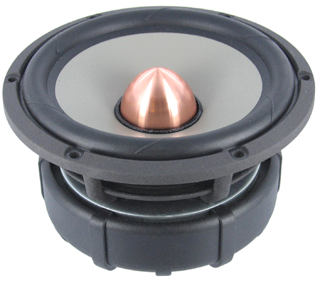
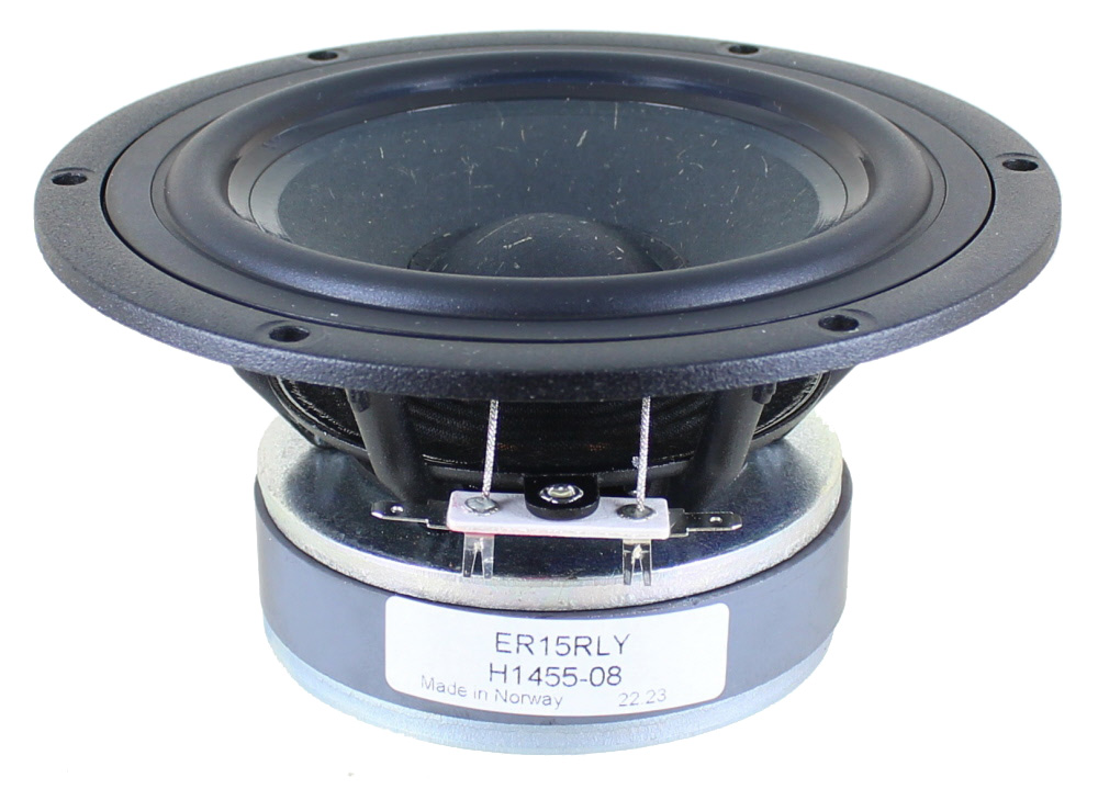
                              Take a look at the big woofer peaks. You can get an idea of the bass output . I think that it’s something along the lines of “tuning” but these are sealed cabinets. The W16 woofer peaks at 85 Hz. The ER15 maxes out at 105 Hz. So we have some idea of the bass extension of the two woofers in the same cabinet. You can predict this result from the T/S parameters and cabinet volume. But now we have real world data. So the W16 deluxe flavor of this speaker should reach about 20 Hz lower than the ER15 flavor. Use this information to pick your subwoofer crossover points accordingly.

                              Image not available
                              Last edited by theSven; 25 June 2023, 17:40 Sunday. Reason: Remove broken image link

                              Comment

                              • JonW
                                Super Senior Member
                                • Jan 2006
                                • 1582

                                cabinet resonances

                                Some more insights from the impedance data… (Again, these are the older baseline upshifted plots but the conclusions are the same.)

                                Looking at the impedance plots, there are some small peaks in the ~700-950 Hz range. A close up is shown below. I suspect that these peaks are from cabinet resonances.

                                The front baffle is 1” thick and the other 5 sides are 3/4” thick Baltic birch ply.

                                I’m thinking about trying to damp down the cabinets a bit. Dynamat certainly comes to mind. Normally, using Dynamat on a speaker gets to be expensive. Not that I’ve tried it. But these speakers are so small, there is not much for area to cover. Plus we need to leave room for mounting the crossovers, drivers, and binding posts. A rough estimate is that a mere $25 might be all it takes to cover what I can with Dynamat for all 4 speakers.

                                An alternative is Whispermat. Which I already have at home. It's foam with some damping layers. Maybe Whispermat on the rear to absorb some of the woofer energy. Then Dynamat on the top, bottom, and sides, wherever there is not a crossover board?

                                Yet another option is to glue in a wooden brace between, say, the left and right panels. But that might be tricky given that the cabinet is already built.

                                I can maybe take impedance plots before and after any of these cabinet damping methods and see if it helps.

                                Any thoughts out there on cabinet damping?

                                Image not available
                                Last edited by theSven; 25 June 2023, 17:40 Sunday. Reason: Remove broken image link

                                Comment

                                • cjd
                                  Ultra Senior Member
                                  • Dec 2004
                                  • 5568

                                  If it's cabinet, it is more likely reflections (though not guaranteed)

                                  Perhaps try a little stuffing first, see if it changes anything. Even the 3/4" 3 layer Sonic Barrier PE offers works really well for both managing reflections and panel resonance.

                                  You can use dowels to brace and that seems it would be ideal for these boxes.

                                  That said, the lower peak would indicate a 19" length, the upper ~14½" or 15¾" - neither strike me as probable in this box, suggesting something else.

                                  Fs is only a nominal indication of how low you can go
                                  diVine Sound - my DIY speaker designs at diVine Audio

                                  Comment

                                  • JonW
                                    Super Senior Member
                                    • Jan 2006
                                    • 1582

                                    Hi Chris,

                                    Thanks for the tips. Yeah, maybe it’s not cabinet resonance but possibly reflections. The ~725 Hz peak is the same for both woofers but the second peak is not at the same frequency. Maybe that indicates that it’s a reflection. Plus your length numbers are not in agreement with my cabinet dimensions.

                                    So maybe I’ll try a layer of Whispermat on the rear and see if that absorbs the reflections some. Plus that should provide a little vibrational damping, I think.

                                    I don’t want to over stuff the cabinet. For my last project, I found that too much stuffing took away some air and made the speaker sound a little lifeless.

                                    Comment

                                    • cjd
                                      Ultra Senior Member
                                      • Dec 2004
                                      • 5568

                                      I'm thinking surround or spider or... something other than box. My dimensions are simple math (frequency wavelength.)

                                      Unsure. I'm a bit over my head for that type of analysis.
                                      diVine Sound - my DIY speaker designs at diVine Audio

                                      Comment

                                      • Face
                                        Senior Member
                                        • Mar 2007
                                        • 995

                                        I'd also recommend 3/4" Sonic Barrier.
                                        SEOS 12/AE TD10M Front Stage in Progress

                                        Comment

                                        • JonMarsh
                                          Mad Max Moderator
                                          • Aug 2000
                                          • 15284

                                          Originally posted by Face
                                          I'd also recommend 3/4" Sonic Barrier.
                                          +1 on that, or WhisperMat, or 1/2" heavy felt or whatever you can scrounge up.

                                          Looks like you've been able to spend some quality thought time on these, if not that much construction time, Jon... sounds familiar, I just got back from Munich yesterday (Saturday night at 11 PM), and obviously didn't do any building or wiring while on travel this last week and a half! On the other hand, had some interesting experiences both at work and outside the office, including some audio stuff, so I can't complain!

                                          Impedance wiggles like you're showing can be due to surround resonance, cone resonance, or reflections; in your case, I'm suspecting the latter. Really small cabinets are more of a problem that way in my experience (like the head module on the Isiris), and require some extra measures for midrange damping- ones that tend to not be good for anything except a sealed alignment. But you're OK in that regard. Basically, the closer to the cabinet wall, the more you're in a low velocity, high pressure zone, and you need different materials than you'd normally stuff the whole cabinet with. I've even found double layers of 1/2" felt to work pretty well. I get the felt from Orchard Hardware, but your local stores may or may not carry that- then you'll have to go online, I guess.
                                          the AudioWorx
                                          Natalie P
                                          M8ta
                                          Modula Neo DCC
                                          Modula MT XE
                                          Modula Xtreme
                                          Isiris
                                          Wavecor Ardent

                                          SMJ
                                          Minerva Monitor
                                          Calliope
                                          Ardent D

                                          In Development...
                                          Isiris Mk II updates- in final test stage!
                                          Obi-Wan
                                          Saint-Saëns Symphonique/AKA SMJ-40
                                          Modula PWB
                                          Calliope CC Supreme
                                          Natalie P Ultra
                                          Natalie P Supreme
                                          Janus BP1 Sub


                                          Resistance is not futile, it is Volts divided by Amperes...
                                          Just ask Mr. Ohm....

                                          Comment

                                          • JonW
                                            Super Senior Member
                                            • Jan 2006
                                            • 1582

                                            Originally posted by cjd
                                            I'm thinking surround or spider or... something other than box. My dimensions are simple math (frequency wavelength.)

                                            Unsure. I'm a bit over my head for that type of analysis.
                                            Originally posted by Face
                                            I'd also recommend 3/4" Sonic Barrier.

                                            Originally posted by JonMarsh
                                            +1 on that, or WhisperMat, or 1/2" heavy felt or whatever you can scrounge up.
                                            Cool. Thanks, guys. I already have a bunch of WhisperMat at home. So that’s what I’ll try. Easy and free (kind of). I’ll guess that it will help, but I’m curious to see the real results.


                                            Originally posted by JonMarsh
                                            Impedance wiggles like you're showing can be due to surround resonance, cone resonance, or reflections; in your case, I'm suspecting the latter. Really small cabinets are more of a problem that way in my experience (like the head module on the Isiris), and require some extra measures for midrange damping- ones that tend to not be good for anything except a sealed alignment. But you're OK in that regard. Basically, the closer to the cabinet wall, the more you're in a low velocity, high pressure zone, and you need different materials than you'd normally stuff the whole cabinet with. I've even found double layers of 1/2" felt to work pretty well. I get the felt from Orchard Hardware, but your local stores may or may not carry that- then you'll have to go online, I guess.
                                            OK, thanks for the perspective. It looks like an issue that is quite easy to address. Unlike, say, fighting with measurements when I have a failing sound card. I will want to find the middle ground between killing these reflections, etc. and not making the speaker sound too damped and dull.

                                            Comment

                                            • JonW
                                              Super Senior Member
                                              • Jan 2006
                                              • 1582

                                              Originally posted by JonMarsh
                                              I just got back from Munich yesterday (Saturday night at 11 PM), and obviously didn't do any building or wiring while on travel this last week and a half! On the other hand, had some interesting experiences both at work and outside the office, including some audio stuff, so I can't complain!
                                              Welcome back. International travel can be fun, interesting... and exhausting. I was in Japan a few months ago. All of us foreigners were waking up at 4 am. Even though we were from the US east coast, the US west coast, and Europe. Try to get some rest.


                                              My weekend is slipping away with lots of work. We’ll see if I can give a shot to the measurements tonight or not. Hmmm.

                                              Originally posted by JonMarsh
                                              Looks like you've been able to spend some quality thought time on these, if not that much construction time, Jon... sounds familiar
                                              These speakers should end up being well thought out. Even if they are not well executed!

                                              Comment

                                              • JonW
                                                Super Senior Member
                                                • Jan 2006
                                                • 1582

                                                Measurements are complete.

                                                No pictures to show for now. Unless someone wants to see raw driver output in the cabinets. It sure is nice to have the measurement step behind me now. Man, with that failing sound card, it took ages to get through the measurements and it was frustrating. Thanks to all of you guys for the help.

                                                Comment

                                                • JonW
                                                  Super Senior Member
                                                  • Jan 2006
                                                  • 1582

                                                  Here are some results from the measurements in case anyone is curious. I wanted to see how things compared side-by-side so I thought that I’d share them.

                                                  The deluxe speakers (W16 woofer), both raw drivers in the cabinets. In the middle of the room.

                                                  Click image for larger version

Name:	DeluxeRaw_zpsfccdc9f9.webp
Views:	79
Size:	42.8 KB
ID:	931419


                                                  The basic speakers (ER15 woofer), both raw drivers in the cabinets. In the middle of the room.

                                                  Click image for larger version

Name:	BasicRaw_zps4b5fcffc.webp
Views:	79
Size:	34.9 KB
ID:	931420


                                                  The deluxe speakers up against a wall. The gating time was opened up to 9 ms. With the extra time you get more noise in the measurements. But the most pertinent thing here is the wall cancellation nulls at ~275, ~440, and ~700 Hz. I’m not sure that there is much to be done about the nulls. But I’ll look into that later. Maybe cook up an insane crossover to fix them. That would be crazy complex, drop the efficiency of the speaker by 30 db, be expensive, and not fit into the cabinet. Maybe just for fun in LspCAD. We’ll see.

                                                  Click image for larger version

Name:	OnWallDeluxeRaw9ms_zps0f6f91dd.webp
Views:	78
Size:	54.0 KB
ID:	931421


                                                  Here are the two woofer swith close up (~1 cm) measurements. The ER15 is in red, on the top and the W16 is in blue on the bottom. Don’t mind the differences in amplitude. (I must have moved something.) It’s hard to make a call here. But I’d say that the ER15 f3 is ~75 Hz and the W16 f3 is ~62 Hz. In these cabinets, the W16 reaches a little deeper. The impedance plots posted earlier also show something similar.

                                                  Click image for larger version

Name:	nearWs_zps86b40103.webp
Views:	75
Size:	40.6 KB
ID:	931422
                                                  Last edited by theSven; 02 April 2023, 12:22 Sunday. Reason: Update image location

                                                  Comment

                                                  • ---k---
                                                    Ultra Senior Member
                                                    • Nov 2005
                                                    • 5202

                                                    I expect you'll have a crossover model worked up any day now and be ordering some parts. :T
                                                    - Ryan

                                                    CJD Ochocinco! ND140/BC25SC06 MTM & TM
                                                    CJD Khanspires - A Dayton RS28/RS150/RS225 WMTMW
                                                    CJD Khancenter - A Dayton RS28/RS150/RS180 WTMW Center

                                                    Comment

                                                    • JonW
                                                      Super Senior Member
                                                      • Jan 2006
                                                      • 1582

                                                      Hey Ryan,

                                                      "Any day now?" We'll see. Work is busy, including 2 trips over the next 2 weeks. But I'll work on them when I can. As far as I know, no one else is building these so there is no hurry. In addition to the crossovers and voicing, I have to deal with that bad tweeter and a few other things here and there. But with the measurements and cabinets done, the rest should be relatively easy and fun. At least that's what I'm thinking now.

                                                      Comment

                                                      • ---k---
                                                        Ultra Senior Member
                                                        • Nov 2005
                                                        • 5202

                                                        That was my subtle prod to keep you progressing. These days, my speaker building is being lived through others like yourself. :wink:

                                                        And so that you know you're not alone, yesterday I did segment #24. Almost all of those are 6:00 am outbound flights. Next week, I got segment 25/26 and 27/28 coming. This weekend, I'm going to be doing drywall mudding. Though I may have to be doing work after my unplanned day off today due to the flooding blocking me in at home. I couldn't make it more than .5 mile in any direction without running into flooding.

                                                        Amazon dropped this off Wednesday. I might have to find time to do some real listening. Had it on yesterday while working and thoroughly enjoying it. JJ Grey reminded me why he is currently one of my top 5 favorites. The audio quality is MUCH better than what comes through on Amazon. I highly recommend it.

                                                        - Ryan

                                                        CJD Ochocinco! ND140/BC25SC06 MTM & TM
                                                        CJD Khanspires - A Dayton RS28/RS150/RS225 WMTMW
                                                        CJD Khancenter - A Dayton RS28/RS150/RS180 WTMW Center

                                                        Comment

                                                        • 5th element
                                                          Supreme Being Moderator
                                                          • Sep 2009
                                                          • 1671

                                                          It's nice when persistance pays off, that's how the FR graphs should look and why I harped on so much about it before, so good job getting it all sorted :T

                                                          Now all that's left is to figure out how to merge near and farfield responses, or can LspCAD6 do this? I know 5.25 can't, still, even with the short gated far-fields, you should be able to come up with a very satisfactory prototype.

                                                          It will be interesting to see if you can somewhat address those impedance bobbles and the dips in the responses with the stuffing/damping materials, as they are the only real fly in the ointment that's left.
                                                          What you screamin' for, every five minutes there's a bomb or something. I'm leavin' Bzzzzzzz!
                                                          5th Element, otherwise known as Matt.
                                                          Now with website. www.5een.co.uk Still under construction.

                                                          Comment

                                                          • fatmarley
                                                            Member
                                                            • May 2011
                                                            • 45

                                                            Hi John,

                                                            Don't know if you remember but you helped me with my measurements a while back

                                                            A couple of things that may help you in the future. I found this calculator: Link It should give you an idea of where to set the gate time.

                                                            As regards to the dip at 275Hz. look up the Allison effect. It's something to consider if you decide to build a 3 way (i'm planning to start one soon)

                                                            Comment

                                                            • JonW
                                                              Super Senior Member
                                                              • Jan 2006
                                                              • 1582

                                                              Originally posted by fatmarley
                                                              Hi John,

                                                              Don't know if you remember but you helped me with my measurements a while back

                                                              A couple of things that may help you in the future. I found this calculator: Link It should give you an idea of where to set the gate time.

                                                              As regards to the dip at 275Hz. look up the Allison effect. It's something to consider if you decide to build a 3 way (i'm planning to start one soon)
                                                              Hi again! Yes, I do remember. After reading through this thread, it’s kind of funny to think that I could help anyone with measurements. (ahem)

                                                              Yup, I know what the origin of the ~275 Hz dip is:
                                                              Genelec loudspeakers are designed for demanding professional, home and AV installation use.


                                                              Two versions of this speaker are going to be designed for on wall placement. I’m trying to think about how I can possibly- if at all- deal with these wall bounce nulls. It may not be possible to do anything about it. But I’m wondering if I can add a bunch of filters to the crossover to, essentially, drop the output everywhere to match the lowest part of the deepest null. Probably difficult and impractical for several reasons. But could be an interesting exercise at least in LspCAD.

                                                              Comment

                                                              • JonW
                                                                Super Senior Member
                                                                • Jan 2006
                                                                • 1582

                                                                Originally posted by 5th element
                                                                It's nice when persistance pays off, that's how the FR graphs should look and why I harped on so much about it before, so good job getting it all sorted :T

                                                                Now all that's left is to figure out how to merge near and farfield responses, or can LspCAD6 do this? I know 5.25 can't, still, even with the short gated far-fields, you should be able to come up with a very satisfactory prototype.

                                                                It will be interesting to see if you can somewhat address those impedance bobbles and the dips in the responses with the stuffing/damping materials, as they are the only real fly in the ointment that's left.
                                                                Thanks! I don’t know if it was “persistence” so much as “stubbornness.” Thanks again for all the help there. The speakers will defintely sound better because of your guidance.

                                                                Right. I still don’t know how to merge the near and far data. Playing around on the computer with a graphing program (Kaleidegraph) it looks as though I can combine the two files into one. But I’m not sure if I can then get that file to be readable in LspCAD because .frd output is not an option. I’ll give it a shot. But if there are other, more standard approaches, I’d like to hear about them. I don’t see a way to do it in LspCAD.

                                                                My guess is that the impedance bobbles will be manageable with Whispermat and such. It’s easy to try a few things there. The only thing I need to watch out for is trying many different things, removing and replacing the woofer several times, and not ending up with stripped wood for the driver screws. I know that there are ways to deal with that (as explained by –k- earlier) but I’d rather avoid the stripping in the first place.

                                                                Which response dips are you referring to and what ways to deal with them do you have in mind? If you mean the nulls from placing the speaker up on a wall, see my comments to fatmarley, above.

                                                                Comment

                                                                • JonW
                                                                  Super Senior Member
                                                                  • Jan 2006
                                                                  • 1582

                                                                  Originally posted by ---k---
                                                                  That was my subtle prod to keep you progressing. These days, my speaker building is being lived through others like yourself. :wink:

                                                                  And so that you know you're not alone, yesterday I did segment #24. Almost all of those are 6:00 am outbound flights. Next week, I got segment 25/26 and 27/28 coming. This weekend, I'm going to be doing drywall mudding. Though I may have to be doing work after my unplanned day off today due to the flooding blocking me in at home. I couldn't make it more than .5 mile in any direction without running into flooding.

                                                                  Amazon dropped this off Wednesday. I might have to find time to do some real listening. Had it on yesterday while working and thoroughly enjoying it. JJ Grey reminded me why he is currently one of my top 5 favorites. The audio quality is MUCH better than what comes through on Amazon. I highly recommend it.

                                                                  http://www.amazon.com/This-River-JJ-...grey+and+mofro
                                                                  Hey Ryan,

                                                                  OK, I’ll keep on with this project. If for no other reason than to make you happy. We are close enough to each other that you may even get to hear these some day.

                                                                  You are also traveling a lot. 28 segments is plenty this early in the year. Let’s see, by the end of next week I think that I’ll be over 20,000 miles so far. Not my favorite way to spend time. Although I’d rather be in a plane than working on drywall.

                                                                  Nice music! Never heard of JJ Grey. A week ago, 3 new CD’s arrived and I can recommend them all. There is the latest from the Eels, something from Buckethead, and a new one from Sallie Ford. I like them all.

                                                                  Comment

                                                                  • 5th element
                                                                    Supreme Being Moderator
                                                                    • Sep 2009
                                                                    • 1671

                                                                    I was more meaning the general dip they both show around 700Hz. This corresponds with an impedance blip and is a little too low in frequency to be diffraction related I believe. If it is a resonance/reflection causing the impedance blip then it is reasonable to assume that the dip in the FR will go away/improve if stuffing/placing absorpative materials is effective in combating the issue.

                                                                    Doing this of course will require more measurements, but if that dip can be eliminated it will certainly make the crossover work easier.

                                                                    You can play with a free program called 'the edge' to simulate diffraction and although not perfect, it should show you enough to see if the peaks/dips you are seeing are diffraction related or otherwise.
                                                                    What you screamin' for, every five minutes there's a bomb or something. I'm leavin' Bzzzzzzz!
                                                                    5th Element, otherwise known as Matt.
                                                                    Now with website. www.5een.co.uk Still under construction.

                                                                    Comment

                                                                    • fatmarley
                                                                      Member
                                                                      • May 2011
                                                                      • 45

                                                                      Jeff Bagby has some great, free software too.

                                                                      Comment

                                                                      • JonW
                                                                        Super Senior Member
                                                                        • Jan 2006
                                                                        • 1582

                                                                        Originally posted by fatmarley
                                                                        Jeff Bagby has some great, free software too.

                                                                        http://audio.claub.net/software/jbabgy/jbagby.html
                                                                        Cool, thanks.


                                                                        Originally posted by 5th element
                                                                        I was more meaning the general dip they both show around 700Hz. This corresponds with an impedance blip and is a little too low in frequency to be diffraction related I believe. If it is a resonance/reflection causing the impedance blip then it is reasonable to assume that the dip in the FR will go away/improve if stuffing/placing absorpative materials is effective in combating the issue.

                                                                        Doing this of course will require more measurements, but if that dip can be eliminated it will certainly make the crossover work easier.

                                                                        You can play with a free program called 'the edge' to simulate diffraction and although not perfect, it should show you enough to see if the peaks/dips you are seeing are diffraction related or otherwise.


                                                                        Ahh, OK. I was wondering if that W16 dip around 700 Hz might be from the impedance bobbles. But the ER15 does not have the dip and does have the impedance bobbles. Does the W16 have a dip at 700 Hz or is it a broad peak at 800-2000 Hz? Looking at the Seas measurement:

                                                                        SEAS Excel W16NX-001 (E0049-08) 6" Magnesium Cone Woofer. Precision cast, machined and surface treated magnesium cone acts as a piston through the audible frequency band without showing any sign of midrange resonances.


                                                                        Ummm. I’m not sure. Yeah, maybe it’s a little dip.

                                                                        My ER15 measurment without the dip looks pretty similar to that from Seas:

                                                                        15 cm (5.5") cone driver, developed for use as a long throw high fidelity woofer or woofer/midrange unit. Edge coated reed/paper pulp cone, together with perfectly matched moving parts gives a smooth, extended frequency response.


                                                                        From my calculations, the ~700-900 Hz impedance blips correspond to ~0.5-0.35 meters in length. Bigger than the largest cabinet dimension. So I imagine that it’s not a diffraction matter.

                                                                        Well, I need to take one speaker apart to have a look at the bad tweeter. Take apart the tweeter and put it back together, seeing if I can get the tweeter impedance to look right. While I’m at it, that might be a good time to remove a woofer, add some Whispermat, and see if the impedance warbles improve any. So maybe the next things to do are:

                                                                        -Try to fix the one bad tweeter. Check with impedance sweeps.
                                                                        -Remove a woofer, add Whispermat, and see if the impedance peaks at 700-900 Hz decrease.
                                                                        -If the Whispermat helps, then retake the measurements.
                                                                        -Then back to crossovers.

                                                                        Comment

                                                                        • 5th element
                                                                          Supreme Being Moderator
                                                                          • Sep 2009
                                                                          • 1671

                                                                          From the latest set of measurements above, both the ER and the W16 show the same dip at around 700Hz and have an impedance wiggle too. It is a little more pronounced in the W16, but it's there in both.
                                                                          What you screamin' for, every five minutes there's a bomb or something. I'm leavin' Bzzzzzzz!
                                                                          5th Element, otherwise known as Matt.
                                                                          Now with website. www.5een.co.uk Still under construction.

                                                                          Comment

                                                                          • JonW
                                                                            Super Senior Member
                                                                            • Jan 2006
                                                                            • 1582

                                                                            Originally posted by 5th element
                                                                            From the latest set of measurements above, both the ER and the W16 show the same dip at around 700Hz and have an impedance wiggle too. It is a little more pronounced in the W16, but it's there in both.
                                                                            Woops. You are correct, sir. For the ER15 speaker, I was looking at the the darker trace. Because the W16 woofer is the dark trace in the above plot. But the dark trace of the ER15 speaker is the tweeter. Which does not have the dip. The ER15 does, indeed, have the dip. Anyways, the plan I outlined above may be the way to go from here.

                                                                            Comment

                                                                            • 5th element
                                                                              Supreme Being Moderator
                                                                              • Sep 2009
                                                                              • 1671

                                                                              Indeed taking impedance measurements will be the easiest way to confirm if anything is working, you may have to get creative and try a few different methods and materials. The area immediately adjacent to the cone (the side and bottom walls at the front of the cabinet) will probably have the most effect and rolling up tight wads of cotton wool or stuffing and placing them along those areas might be needed. Covering the top side of the magnet/top plate may also help. It's not that the magnet will be causing the problem, more the close proximity of the magnet and the side walls to the cone making a sort of cavity. This may be one of the times where a small neo, or SEAS hexadym magnet may actually help.

                                                                              Between measurements and stuffing tries you don't have to screw in the driver, having the cabinet lying flat on its back and holding it firmly in place should be more than enough. That should help with the screw holes from being stripped.
                                                                              What you screamin' for, every five minutes there's a bomb or something. I'm leavin' Bzzzzzzz!
                                                                              5th Element, otherwise known as Matt.
                                                                              Now with website. www.5een.co.uk Still under construction.

                                                                              Comment

                                                                              • JonW
                                                                                Super Senior Member
                                                                                • Jan 2006
                                                                                • 1582

                                                                                Originally posted by 5th element
                                                                                Indeed taking impedance measurements will be the easiest way to confirm if anything is working, you may have to get creative and try a few different methods and materials. The area immediately adjacent to the cone (the side and bottom walls at the front of the cabinet) will probably have the most effect and rolling up tight wads of cotton wool or stuffing and placing them along those areas might be needed. Covering the top side of the magnet/top plate may also help. It's not that the magnet will be causing the problem, more the close proximity of the magnet and the side walls to the cone making a sort of cavity. This may be one of the times where a small neo, or SEAS hexadym magnet may actually help.

                                                                                Between measurements and stuffing tries you don't have to screw in the driver, having the cabinet lying flat on its back and holding it firmly in place should be more than enough. That should help with the screw holes from being stripped.
                                                                                Thanks for all the tips. They make good sense, but I didn't know about any of that. So I've learned something.

                                                                                I'm just back from one work trip but soon out on another. We'll see when I can get to try out these things. I haven't had a day off from work in maybe 2 months. I'm starting to wear down. Maybe a day with the speakers is what is needed.

                                                                                Comment

                                                                                • JonW
                                                                                  Super Senior Member
                                                                                  • Jan 2006
                                                                                  • 1582

                                                                                  Here is the latest…

                                                                                  The good news:
                                                                                  I got a few hours to work on the speakers.

                                                                                  The bad news:
                                                                                  I removed the suspect tweeter from the cabinet, took it apart and put it back together several times. Taking many impedance sweeps along the way. I can get that second hump to decrease but not go away completely. If I put the tweeter back together incorrectly, the impedance looks very off, with multiple peaks. Sometimes it looks kind of OK, but then I put it into the cabinet or just measure it again and that unwelcome peak appears again. On a side note, it’s scary taking apart an expensive Scanspeak tweeter. Beyond my pay grade, I think. Anyways, I think that I’m going to have to order a replacement tweeter. Oh well, but not the end of the world.

                                                                                  The middle news:
                                                                                  I experimented with some stuffing to try and decrease the impedance spikes in the ~700-950 Hz range. Turns out that the cabinet is really tight, with the woofer magnet almost touching both sides and the bottom. (I can post photos if anyone wants to see.) And the W16 woofer magnet is almost as wide as the mounting flange. I tried adding Whispermat below the woofer and on the cabinet sides but there was no space at all for that. Also, I tried putting some Whispermat around the woofer magnet. Even when I shaved it down to ~3/4” thickness, it was still too big to allow the woofer to go onto the cabinet hole. I realize that the small cabinet nature of this project brings about some compromises and here is one. Not a big deal. You pick your priorities and go from there. Small was a major factor for this project.

                                                                                  By the way, the 1 1/4” thick “Whispermat” that I am using might actually be Parts Express Sonic Barrier. I’ve got to go back through some old orders and see what I bought.

                                                                                  What I could do was cut out a piece of the Whispermat to cover the entire rear of the cabinet, a 9” x 5” piece. When I put that in there, the impedance peaks did change a bit versus not having anything in there. Graphs are below. My graphing program doesn’t like the WooferTester files so don’t mind that the graphs look funny.

                                                                                  So it looks as though I was able to decrease the impedance peaks a little. I’m wondering:

                                                                                  -Is this improvement anything significant or not really much? Keep the stuffing? I'll guess that it's looking better and I should keep the Whispermat.

                                                                                  -Is the low frequency increase in impedance with stuffing, below the main peak, anything to be concerned about? Related to that, the main peak has decreased in intensity. Have I solved one problem only to have created another?

                                                                                  -Should I take new frequency response/microphone measurements with the stuffing in there? Before moving on to crossovers. I suspect so.

                                                                                  Thanks!

                                                                                  Click image for larger version

Name:	StuffingCloseup_zpsbc4aacff.webp
Views:	77
Size:	19.3 KB
ID:	931423

                                                                                  Click image for larger version

Name:	StuffingLarge_zps62b1b5f4.webp
Views:	76
Size:	20.1 KB
ID:	931424
                                                                                  Last edited by theSven; 02 April 2023, 12:24 Sunday. Reason: Update image location

                                                                                  Comment

                                                                                  • 5th element
                                                                                    Supreme Being Moderator
                                                                                    • Sep 2009
                                                                                    • 1671

                                                                                    The appearance of any additional resonance is always troubling, if it has any real impact will only really come through with FR measurements. I didnt realise that things were so cramped around the back-end, it's not a surprise that you're seeing reflection issues.

                                                                                    The W16 comes with a rubber boot, would it be possible to remove the boot to gain a few extra mm of breathing space?

                                                                                    It's a shame about the scan tweeter, it sounds like part of it was deformed so that the voice coil was rubbing.
                                                                                    What you screamin' for, every five minutes there's a bomb or something. I'm leavin' Bzzzzzzz!
                                                                                    5th Element, otherwise known as Matt.
                                                                                    Now with website. www.5een.co.uk Still under construction.

                                                                                    Comment

                                                                                    • JonW
                                                                                      Super Senior Member
                                                                                      • Jan 2006
                                                                                      • 1582

                                                                                      Originally posted by 5th element
                                                                                      The appearance of any additional resonance is always troubling, if it has any real impact will only really come through with FR measurements.
                                                                                      Yes, the additional resonance is concerning me. Maybe because I don’t really understand it. I’m tempted to rip out the Whispermat and just go with the measurements that I already have. Kind of like “the devil that you know.” But maybe the best way to proceed is take new measurements of the speakers with Whispermat in them. Then see which FR measurements look better- with versus without the Whispermat. Then decide which way to go?


                                                                                      Originally posted by 5th element
                                                                                      I didnt realise that things were so cramped around the back-end, it's not a surprise that you're seeing reflection issues.
                                                                                      Yeah, it’s really tight in there. The photos below (posted already) might give you an idea. I have some better photos to show it, on another computer. The front rabbet for mounting the driver overlaps with the side walls. And the W16 has one monster-sized magnet that just fits into the hole. There is very little clearance between the magnet and the sides. A little more clearance to the bottom but not much.

                                                                                      Small is the major design constraint here. There is a reason that people make big speakers. So I realize, going into this project, that there will be some compromises. But making the best possible speaker with the smallest possible footprint is kind of part of the fun puzzle here.


                                                                                      Originally posted by 5th element
                                                                                      The W16 comes with a rubber boot, would it be possible to remove the boot to gain a few extra mm of breathing space?
                                                                                      I’ll take a look the next time I have them opened up. It’s probably there for a good reason, I’d think. After taking apart that tweeter, into all its bits, I’m kind of hesitant to mess with the drivers more. And the W16 costs twice what those tweeter do. 8O

                                                                                      Originally posted by 5th element
                                                                                      It's a shame about the scan tweeter, it sounds like part of it was deformed so that the voice coil was rubbing.
                                                                                      Yeah, it’s annoying but, other than the time I wasted, not a big deal. It’s only money. (ahem)


                                                                                      Click image for larger version  Name:	fetch?id=931365&d=1680446635.webp Views:	2 Size:	25.3 KB ID:	942919

                                                                                      Click image for larger version  Name:	fetch?id=931366&d=1680446659.webp Views:	2 Size:	38.9 KB ID:	942920
                                                                                      Last edited by theSven; 25 June 2023, 18:11 Sunday. Reason: Update image location

                                                                                      Comment

                                                                                      • ---k---
                                                                                        Ultra Senior Member
                                                                                        • Nov 2005
                                                                                        • 5202

                                                                                        Progress.

                                                                                        Either the 4or 8 ohm version of the RS drivers came with a rubber boot. CJD told me it was for the car audio guys. I'm not sure why, but that is what I remember. I'm pretty sure you can get rid of them.

                                                                                        I'm not an expert on measurements, but I don't think you have to retake them for such a small change in the stuffing and impedance. If your curious, I guess.

                                                                                        Sent from my Kindle Fire using Tapatalk 2
                                                                                        - Ryan

                                                                                        CJD Ochocinco! ND140/BC25SC06 MTM & TM
                                                                                        CJD Khanspires - A Dayton RS28/RS150/RS225 WMTMW
                                                                                        CJD Khancenter - A Dayton RS28/RS150/RS180 WTMW Center

                                                                                        Comment

                                                                                        • 5th element
                                                                                          Supreme Being Moderator
                                                                                          • Sep 2009
                                                                                          • 1671

                                                                                          The rubber boot, is a K says, most likely from the car audio sector, where they are used to prevent the magnets from possibly getting bashed and chipping. In home audio they arent needed but could possibly dampen some very benign resonances in the basket/motor structure. In this case it will most likely be restricting the air flow around the driver. I mean I know the boot is probably 5mm at max, but if it's almost pressed into the cabinet edge, I'd be happy to take those 5mm!

                                                                                          From my point of view FR measurements are the only way you will know that what you're doing is being in any way effective. If the size of the dip in the FR is proportional to the size of the impedance blip then you may have reduced its effect by a couple of dB.

                                                                                          One thing I will point out here is that stuffing usually results in an increase of effective box volume and should lower the system resonance. Your stuffing has apparently increased the resonance slightly and reduced the magnitude of the impedance peak, which I think would help support the theory that you are restricting the actual air flow from the rear of the driver into the effective cabinet volume.

                                                                                          This should be less of an issue with the ER15, but I think it helps point out that if you can remove the boot then it'd be a very good idea. I think it shows that you do need to balance the amount of stuffing that you are using so close to the opening of the cone at the rear of the driver. I mean its necessary in reducing the reflections (how effective this is in the FR domain we don't know yet), but at the same time, if you over do it you start affecting other things. You could perhaps remove the boot and then surround the magnet, inculding the top plate, with felt and this might help with the reflections.

                                                                                          Personally, I would opt for decreasing the resonances (if they do affect the FR) and accept the down sides of a bit of over stuffing. It might be worth running a nearfield FR measurement with the stuffing in place and compare it with the version without the stuffing, just so you can see how much it actually affects the box alignment. I will point out though that restricting the air flow round the back of the driver, via resistive means, is not a bad thing as per say (like the resonance are) it's just a different way of affecting the driver+box tuning, just like stuffing different densities of open cell foam into ports can be a very effective way at reducing their output.
                                                                                          What you screamin' for, every five minutes there's a bomb or something. I'm leavin' Bzzzzzzz!
                                                                                          5th Element, otherwise known as Matt.
                                                                                          Now with website. www.5een.co.uk Still under construction.

                                                                                          Comment

                                                                                          • JonW
                                                                                            Super Senior Member
                                                                                            • Jan 2006
                                                                                            • 1582

                                                                                            Originally posted by ---k---
                                                                                            Progress.

                                                                                            Either the 4or 8 ohm version of the RS drivers came with a rubber boot. CJD told me it was for the car audio guys. I'm not sure why, but that is what I remember. I'm pretty sure you can get rid of them.

                                                                                            I'm not an expert on measurements, but I don't think you have to retake them for such a small change in the stuffing and impedance. If your curious, I guess.
                                                                                            Ah, OK, for the car guys. A world that I know little about. Yup, I can pull off the rubber boot.

                                                                                            From what 5thelement is saying and from what we might guess, the stuffing, at least in this case, might make up to a 2 db difference. Is that worth new measurements? Probably a different answer for different people and different projects. I think that I’ve got a plan cooked up.

                                                                                            More details in a moment...

                                                                                            Comment

                                                                                            Working...
                                                                                            Searching...Please wait.
                                                                                            An unexpected error was returned: 'Your submission could not be processed because you have logged in since the previous page was loaded.

                                                                                            Please push the back button and reload the previous window.'
                                                                                            An unexpected error was returned: 'Your submission could not be processed because the token has expired.

                                                                                            Please push the back button and reload the previous window.'
                                                                                            An internal error has occurred and the module cannot be displayed.
                                                                                            There are no results that meet this criteria.
                                                                                            Search Result for "|||"