Ergo's Wavecor Ardent Build

Collapse
X
 
  • Time
  • Show
Clear All
new posts
  • ergo
    Senior Member
    • Mar 2005
    • 676

    Ergo's Wavecor Ardent Build

    With the weather conditions finally replicating the ones in CA the time is right to finally replicate the Wavecor Ardents up here in north

    I do love the Fusion 360 and it's CAD -> CAM -> CNC machine workflow. I started things off with the front panel milling jobs. My machine can't take the full lenght of the front panel, but it does enough to do tw + mid + 2 woofer and a bit more. I do have to shorten the center brace a bit or extend the slot with manual router.

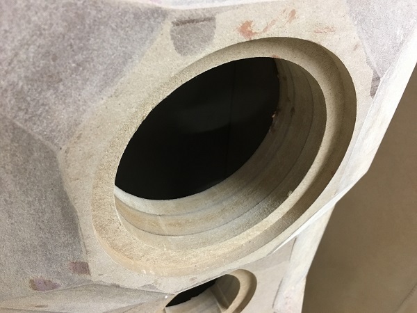
    The final front panel and speaker recess tuning is a breeze as one has such a good control of the CAM - CNC and by making a test piece I could fine tune the driver holes.

    I'm building 4 front panels (and two boxes). Reasoning is that usually the 3rd attempt and later are the one's that come out good. So by making 4 the hope is that at least 2 succeed. If all come out ok then I'm sure there might be some interested parties somewhere in Europe to offload those two. This project is quite popular after all ...

    Glue up is in progress and front panel cutting to dimensions and the bevel cuts will be attempted. My hand saw on a track falls a bit short of being able to cut the 70mm depth, so even the 90deg edges need cutting from both sides. Table saw would be able to cut through, but I'm more afraid of getting them through that as the DeWalt top plate is not big enough to support this type of job too good.

    Click image for larger version

Name:	weather.jpg
Views:	1
Size:	26.7 KB
ID:	872281Click image for larger version

Name:	F360_CAM_front.jpg
Views:	1
Size:	57.9 KB
ID:	872282Click image for larger version

Name:	FP layer 4.jpg
Views:	1
Size:	60.7 KB
ID:	872283Click image for larger version

Name:	tw_mid_cutout trial.jpg
Views:	1
Size:	56.4 KB
ID:	872284Click image for larger version

Name:	tw_mid_cutoout_trial_after.jpg
Views:	1
Size:	60.0 KB
ID:	872285
  • ergo
    Senior Member
    • Mar 2005
    • 676

    #2
    Front panel build process

    Front panels glued up. I did use two centering pins to help align the layers. As I had 6mm alu tube leftover then dowels came out of that this time.

    When doing the top bevels with Mafell saw on a track I first did a mistake and did not move the track as I set the saw blade deeper. When the tooth of the blade come out of the material they have an upward force and that caused small splinters to loosen from front panel top layer.

    To solve that I ran the next runs so that with a first cut the blade made a small V groove into top layer. Then I adjusted the track to be offset by a small margin (1/3 of a mm or so). That is enough to avoid the sawtooth picking up splinters when surfacing from material and I did not have the same issue with any of the next cuts.

    Click image for larger version

Name:	centering pins on FP_l4.jpg
Views:	1
Size:	98.7 KB
ID:	863590
    Click image for larger version

Name:	glueup_clamps.jpg
Views:	1
Size:	146.2 KB
ID:	863591
    Click image for larger version

Name:	bevel_cut_fail.jpg
Views:	1
Size:	66.3 KB
ID:	863592
    Click image for larger version

Name:	bevel_cut_skim.jpg
Views:	1
Size:	53.6 KB
ID:	863593
    Click image for larger version

Name:	bevel_cut_with_offset.jpg
Views:	1
Size:	66.4 KB
ID:	863594
    Last edited by ergo; 20 July 2018, 14:25 Friday.

    Comment

    • ergo
      Senior Member
      • Mar 2005
      • 676

      #3
      Front panel bevel cuts

      After lots of contemplation on bevel cuts I went for Bob Ellis method. Using the Japanese hand saw to cut a rough bevel angles and leaving quite a generous safety reserve.

      Then powered hand planer to take it close to the marked lines. And then in end a sanding paper glued to a long piece of plywood.

      This method seemed safer than the jobsite Dewalt + a jig as balancing these heavy long pieces would be a challenge.

      One learning from the process is perhaps that the top bevels should be left for later as it will be easier to mark the bevel cut lines. Including one to the top edge. As I had cut the top bevels already I had to rely only on the lines on front face and side face as guides and start the sawing from the narrow end... Starting from the wide end like I could do on the bottom bevel was easier as it is easier to get a good cut angle going.

      Click image for larger version

Name:	japanese saw bevel cut.jpg
Views:	1
Size:	54.9 KB
ID:	863598Click image for larger version

Name:	IMAG1254.jpg
Views:	1
Size:	58.1 KB
ID:	863601Click image for larger version

Name:	IMAG1257.jpg
Views:	1
Size:	85.7 KB
ID:	863602Click image for larger version

Name:	first_two_bevels_done_angle.jpg
Views:	1
Size:	51.8 KB
ID:	863600Click image for larger version

Name:	first_two_bevels_done_front.jpg
Views:	1
Size:	54.3 KB
ID:	863599
      Last edited by ergo; 23 July 2018, 14:44 Monday.

      Comment

      • ergo
        Senior Member
        • Mar 2005
        • 676

        #4
        Box build - dado set in action

        Current plan is still do leave the BB ply also as a final finish, so I got a chance to use the Dado set I brought along from one of the US visits. Cut Dado grooves to the front panel, back panel and sides. Should help with glue up and looks better imho than leaving the full 17.5mm BBply visible on corners.

        Not much to comment here. Pictures tell the story.

        Click image for larger version

Name:	Dado stack.jpg
Views:	1
Size:	40.3 KB
ID:	863603Click image for larger version

Name:	Dado_cut.jpg
Views:	1
Size:	89.1 KB
ID:	863604Click image for larger version

Name:	Dado_test.jpg
Views:	1
Size:	41.1 KB
ID:	863605Click image for larger version

Name:	FP_Dados.jpg
Views:	1
Size:	42.6 KB
ID:	863606Click image for larger version

Name:	Outer_shell_dry_fit.jpg
Views:	1
Size:	70.6 KB
ID:	863607
        Last edited by ergo; 23 July 2018, 14:50 Monday.

        Comment

        • ergo
          Senior Member
          • Mar 2005
          • 676

          #5
          Box internals

          Some further progress done.

          After dry fit and cutting all the dado-s and braces etc I first attached the MDF to side and back with few screws. Then after disassembly replaced those with wood dowels to keep them lined up also when gluing.

          Todays progress was getting all the holes done and rounded on all the braces. "Speaker B" shell is glued up. Back panel and front panel glue-up still to come. And then the same for "Speaker A"

          I did change the middle braces somewhat. Also left a potential place for the Hypex plate amp for the woofer... Currently the plan has changed to still go for the full passive speaker first.

          Click image for larger version

Name:	dry_fit_2.jpg
Views:	1
Size:	56.9 KB
ID:	863612Click image for larger version

Name:	side_bacl_glueup.jpg
Views:	1
Size:	99.8 KB
ID:	863613Click image for larger version

Name:	bracing.jpg
Views:	1
Size:	82.5 KB
ID:	863614Click image for larger version

Name:	mid_back_wall.jpg
Views:	1
Size:	130.9 KB
ID:	863616Click image for larger version

Name:	bracing+mid_box.jpg
Views:	1
Size:	105.1 KB
ID:	863615
          Last edited by ergo; 26 July 2018, 14:36 Thursday.

          Comment

          • ergo
            Senior Member
            • Mar 2005
            • 676

            #6
            Box final assembly

            Progress is slow but steady. Now all of the box assembly glue jobs are done. Also bases got milled and glued. 10 large head furniture bolts are used for attaching the base

            Some learnings along the way were that even if one dry assembles every thing and it fits super nice, the glue-up of the sandwitch layer of MDF will warp the panels somewhat and makes it hard to assemble these later. So probably a better process would be to make temporary spacers to keep the sides parallel for front and back panel later. Then glue up all of the external ring of side-top-bottom-side and then build and glue the MDF round inside leaving a bit more leeway there. I cut the MDF too precise and that gave more issues and needed some tweaking. Otherwise it would have caused some problems with exterior ring of BB and dado cut fits.

            Click image for larger version

Name:	Gluep_of_back_panels.jpg
Views:	1
Size:	82.8 KB
ID:	863629Click image for larger version

Name:	Bessey_angle.jpg
Views:	2
Size:	54.8 KB
ID:	863630Click image for larger version

Name:	Box_glueup_done_1.jpg
Views:	1
Size:	88.0 KB
ID:	863631Click image for larger version

Name:	base_done.jpg
Views:	1
Size:	55.4 KB
ID:	863633Click image for larger version

Name:	pair_bases_done.jpg
Views:	1
Size:	71.2 KB
ID:	863634
            Last edited by ergo; 29 July 2018, 13:42 Sunday.

            Comment

            • ergo
              Senior Member
              • Mar 2005
              • 676

              #7
              Finishing touches

              Box build part got finished today with final coats of Osmo oil/wax application. I had not tried this one before, so started with trials on leftover pieces. The test was good and the end result is also exactly what I aimed for - ie protecting the wood but keeping the natural color and wood grain of the BB ply.

              Click image for larger version

Name:	Osmo.jpg
Views:	1
Size:	40.2 KB
ID:	863669Click image for larger version

Name:	Osmo_on_1.jpg
Views:	1
Size:	39.6 KB
ID:	863670Click image for larger version

Name:	Osmo_on_2.jpg
Views:	1
Size:	33.7 KB
ID:	863671Click image for larger version

Name:	Osmo_on_4.jpg
Views:	1
Size:	35.9 KB
ID:	863672
              Last edited by ergo; 05 August 2018, 11:21 Sunday.

              Comment

              • ergo
                Senior Member
                • Mar 2005
                • 676

                #8
                Final outcome

                Drive units installed. With 3 pairs of terminals on back I could wire the tweeter / mid and woofers each to one terminal. Will make it easy to do verification measurements and then build and listen to xover outside the box for a start.

                Click image for larger version

Name:	Drivers_in.jpg
Views:	2
Size:	39.2 KB
ID:	863679
                Last edited by ergo; 12 August 2018, 12:46 Sunday.

                Comment

                • 5th element
                  Supreme Being Moderator
                  • Sep 2009
                  • 1671

                  #9
                  Those rebates look very well done!
                  What you screamin' for, every five minutes there's a bomb or something. I'm leavin' Bzzzzzzz!
                  5th Element, otherwise known as Matt.
                  Now with website. www.5een.co.uk Still under construction.

                  Comment

                  • Steve Manning
                    Moderator
                    • Dec 2006
                    • 1891

                    #10
                    Very nice Ergo. What's the working envelop of your CNC out of curiosity? As a suggestion, have you considered using alignment dowels for the different layers? That way you don't have to mess with having to cut the entire baffle to size after glue up. I did that for the Ardent baffles I did and it worked nicely .... also your talking by hand and not CNC so I had a lot more room for error.
                    Hold on to your butts - It's about to get Musical!


                    WEBSITE: http://www.smjaudio.com/

                    Comment

                    • ergo
                      Senior Member
                      • Mar 2005
                      • 676

                      #11
                      I did use the centering pins, but will need to cut the panels to size anyhow because I ordered the initial stock over sized a bit.

                      The CNC has a working area of 995mm * 595mm (approx 39in x 23in), so good for a stand mount speaker but falling a bit shy for this type of floor stander build.

                      ***

                      I did discover yesterday that all my logic of building 4 panels instead of 2 did not quite work out the way intended due to my own process error. I had set the CNC zero-zero position to the center of the tweeter while the cutting paths all used a centering pin as zero. So all of my driver holes on panels are 63.4mm (ca 2.5in) lower than intended.

                      Learning here is that if I would have followed the correct logic of making multi panels - meaning milling one only and then drawing all bevel cuts on it etc I would have found the mistake... but of course in middle of things I thought it's a good idea to process all 4 of each layer at one go. I do have an idea how to 'fix this' by growing that amount of material back to the bottom.

                      Click image for larger version

Name:	CNc_mistake.jpg
Views:	1
Size:	4.2 KB
ID:	863680
                      Last edited by ergo; 12 August 2018, 12:47 Sunday.

                      Comment

                      • Bukem
                        Member
                        • Mar 2008
                        • 89

                        #12
                        Any chance to give the rear of the drivers some more space to breathe?

                        Comment

                        • ergo
                          Senior Member
                          • Mar 2005
                          • 676

                          #13
                          I did try to open up the back of mid by making the holes gradually bigger and rounding over the sharp corner too.

                          Jon had to make a trade off between thick panel and how open the drivers can be. For woofers there is not much room to widen the holes as the existing hole size comes close to side panel already (as those are thick too). As the woofer operate in 250Hz and below, the opening and chamfering around them will have less of an effect too due to wavelenght.

                          Click image for larger version

Name:	mid_opening_back.jpg
Views:	1
Size:	64.1 KB
ID:	863595

                          Comment

                          • JonMarsh
                            Mad Max Moderator
                            • Aug 2000
                            • 15284

                            #14
                            This is looking quite good! The devil is in the details when trying to manage a CNC process (or even manual cutting) and it's easy for one slip on a detail to create problems- I hope your recovery on this issue goes smoothly. I'm happy to see you are making progress- sometimes the press of life makes it quite hard to find time for this activity- (that's been what's happening to me- we're still down 40% on our technical team, and I've even taken to active recruiting efforts myself (not my job, needless to say) but may have issues with our VP regarding the results- a very talented candidate that every one wants, but like a number of other AE's and marketing people, would be remotely located in their region, not in the HQ).

                            Turn about is fair play- I've got a big stack of Minerva finished cabinets and parts that I would really like to turn into working speakers, but finding any time for that in the last six months has completely eluded me!
                            the AudioWorx
                            Natalie P
                            M8ta
                            Modula Neo DCC
                            Modula MT XE
                            Modula Xtreme
                            Isiris
                            Wavecor Ardent

                            SMJ
                            Minerva Monitor
                            Calliope
                            Ardent D

                            In Development...
                            Isiris Mk II updates- in final test stage!
                            Obi-Wan
                            Saint-Saëns Symphonique/AKA SMJ-40
                            Modula PWB
                            Calliope CC Supreme
                            Natalie P Ultra
                            Natalie P Supreme
                            Janus BP1 Sub


                            Resistance is not futile, it is Volts divided by Amperes...
                            Just ask Mr. Ohm....

                            Comment

                            • ergo
                              Senior Member
                              • Mar 2005
                              • 676

                              #15
                              Jon, nice to see you reading/writing to the forum in along time They really do push you hard at work and don't leave 'time to play'... that might backfire one day I guess.

                              As for the positioning mistake - current plan ongoing already is to take a piece from top and glue it to bottom (done). Then cut a small V groove around the panel at this junction. Later when speakers are ready I'll either CNC myself or order a project tag of "Wavecor Ardent" and place that on that extra bottom section. Will give that part a job and if in luck will serve as an extra design detail.

                              Comment

                              • ergo
                                Senior Member
                                • Mar 2005
                                • 676

                                #16
                                Added some progress pics above. Outside shells of the box done and tomorrow I'll have a go with the MDF layer inside and the mid box + bracing.

                                Comment

                                • ergo
                                  Senior Member
                                  • Mar 2005
                                  • 676

                                  #17
                                  This is how I solved the cut/glue line to fix the wrong placements on the panels and the piece glued to bottom.

                                  I added a small v-Groove around the front faces. Used a trick with hot glue gun to attach the "guide rail" for the router. Learned that from Jimmy Diresta probably. Perhaps of use to someone one of these days.

                                  Click image for larger version

Name:	v-goove_guide.jpg
Views:	1
Size:	81.0 KB
ID:	863617Click image for larger version

Name:	v-groove.jpg
Views:	1
Size:	67.7 KB
ID:	863618

                                  Comment

                                  • Dave Bullet
                                    Senior Member
                                    • Jul 2007
                                    • 474

                                    #18
                                    Most impressive! You've got some great tools there and skills to go with it. Will follow this with interest.

                                    Comment

                                    • ergo
                                      Senior Member
                                      • Mar 2005
                                      • 676

                                      #19
                                      Bessey clamps are great

                                      Added some progress pics above.

                                      I do love those Bessey parallel clamps and also the small speed clamps that I invested in last autumn (originally mostly with this project in mind). These have made the whole build process much more smooth and even though expensive I do consider these to have already paid themselves off with the "good clamping" they do.

                                      Note the one holding one of the more stubborn upper corners. With these small extra pieces the parallel clamps become useful for clamping something not quite so parallel.

                                      Click image for larger version

Name:	Bessey_angle.jpg
Views:	2
Size:	54.8 KB
ID:	863632

                                      Comment

                                      • meb46
                                        Senior Member
                                        • Jul 2010
                                        • 398

                                        #20
                                        Very nice work ergo... keep the progress pictures coming!!!

                                        Comment

                                        • ergo
                                          Senior Member
                                          • Mar 2005
                                          • 676

                                          #21
                                          Speaker terminals

                                          In addition to getting the bases done (see above) I also milled out a pair of custom terminal panels from a darkened plexiglass.
                                          It gives me readiness to add a Hypex FA251 plate amp for woofer duties, but it will be possible to bypass that and feed the woofers direct (as passive xover will be in place for lows also).

                                          At first go 2 pairs of terminals will be great as I can assemble and test the xover externally and wire each driver to one pair of terminals.

                                          I also milled out a template to use for sinking the terminal panel into the speaker box. At first go I used a bit of electric tape around the guide bushing and once the rough cleanout was done I removed it. ... similar strategy as the CAM softwares use for CNC milling where it first makes the 'roughing' and the in end a sideways 'clean pass' at the intended depth.

                                          Click image for larger version

Name:	terminal_plate_milling.jpg
Views:	1
Size:	72.5 KB
ID:	863635Click image for larger version

Name:	terminal_plate_trial.jpg
Views:	1
Size:	91.3 KB
ID:	863637Click image for larger version

Name:	terminal_plate_template.jpg
Views:	1
Size:	63.5 KB
ID:	863636

                                          Comment

                                          • TEK
                                            Super Senior Member
                                            • Oct 2002
                                            • 1670

                                            #22
                                            Nice progress Ergo!
                                            It’s always something magical about seeing new Ardens coming to life:-)
                                            -TEK


                                            Many of the great achievements of the world were accomplished by tired and discouraged men who kept on working...

                                            Comment

                                            • ergo
                                              Senior Member
                                              • Mar 2005
                                              • 676

                                              #23
                                              Thanks guys!

                                              Current progress is that one of the two speakers has been sanded down to 120grit (ie glue cleanup and general almost final smoothness). Other one is still to do. Now daily work started again, so that will slow things again.

                                              I'm now going through the xover shopping list. My stepdaughter is coming over from LA at end of month, so I probably get her to carry some ERSE inductors over from US. Most stuff I'll try to find from Audiohobby page as thats close to me and I can pick up parts even in person

                                              Comment

                                              • ergo
                                                Senior Member
                                                • Mar 2005
                                                • 676

                                                #24
                                                Added some pictures after the final finishing above. As usual it's hard to do justice to the look of these via photo. I must say I'm a fan of Osmo oli/wax now.

                                                Leaving the plywood bare might be not to everyone's liking, but we live close enough to Skandinavia and like the "Skandinavian design" where one can often find plywood exposed. My wife unit is willing to accept these new puppies in premium spots in family room so that is an achievement in itself

                                                Comment

                                                • crackyflipside
                                                  Senior Member
                                                  • Nov 2006
                                                  • 197

                                                  #25
                                                  Wonderful job on that cabinet!
                                                  -Chris B

                                                  ;x( DIY

                                                  Comment

                                                  • Juhazi
                                                    Senior Member
                                                    • May 2008
                                                    • 239

                                                    #26
                                                    Osmo oil/wax is my favourite finish for plywood or veneer too. Often I first apply some stain, I like Liberon products. I apply stain and Osmo by rubbing with cloth/rags. Some practise needed but not too hard to do really, much easier than painting with brush or spraying. Several layers of Osmo is needed, I rub first two layer almost off before it is fully dry, this way I get better penetration of wax and smoother finish.
                                                    Last edited by Juhazi; 06 August 2018, 10:40 Monday.
                                                    My DIY speaker history: -74 Philips 3-way, -82 Hifi 85B, -07 Zaph L18, -08 Hifitalo AW-7, CSS125FR, -09 MarkK ER18DXT, -13 PPSL470Dayton, -13 AINOgradient, -18 Avalanche AS-1 dsp, -18 MR183w

                                                    Comment

                                                    • ergo
                                                      Senior Member
                                                      • Mar 2005
                                                      • 676

                                                      #27
                                                      Thanks Juhazi for good tips. I'll keep in mind for next project (be it speakers or something else).

                                                      I did apply 3 coats in end and quite pleased with it, but I'm pretty sure there are things to learn still. Rubbing the first layers more might be good indeed. I also need to find a better source for a suitable non abrasive, no lint material to use for this.

                                                      Comment

                                                      • Juhazi
                                                        Senior Member
                                                        • May 2008
                                                        • 239

                                                        #28
                                                        Old white cotton t-shirt or bed sheets are "the standard" I guess
                                                        My DIY speaker history: -74 Philips 3-way, -82 Hifi 85B, -07 Zaph L18, -08 Hifitalo AW-7, CSS125FR, -09 MarkK ER18DXT, -13 PPSL470Dayton, -13 AINOgradient, -18 Avalanche AS-1 dsp, -18 MR183w

                                                        Comment

                                                        • ergo
                                                          Senior Member
                                                          • Mar 2005
                                                          • 676

                                                          #29
                                                          Drivers are in the boxes and ready for measurement session. The boxes are cool without the drivers, but once those are in it does look better yet

                                                          Click image for larger version

Name:	Drivers_in.jpg
Views:	2
Size:	39.2 KB
ID:	863681

                                                          Comment

                                                          • Horio
                                                            Senior Member
                                                            • Sep 2014
                                                            • 158

                                                            #30
                                                            Looking great ergo! Your Ardent's are turning out great. Looks like its time for them to start singing.

                                                            Comment

                                                            • ergo
                                                              Senior Member
                                                              • Mar 2005
                                                              • 676

                                                              #31
                                                              Box only - without drivers - 37kg each (81.5pounds)
                                                              Woofer - 4.4kg each --> x2 = 8.8kg
                                                              Midrange - 1.8kg
                                                              Box + drivers = ca 47.6kg (105pounds)

                                                              These speakers are heavy! So I created pair of 'moving plates' to ease moving them around for the measurements and perhaps also first listening stage. Some old bamboo material from a failed job on CNC found it's new use.

                                                              Click image for larger version

Name:	moving_plate.jpg
Views:	1
Size:	41.8 KB
ID:	863682

                                                              Comment

                                                              • BobEllis
                                                                Super Senior Member
                                                                • Dec 2005
                                                                • 1609

                                                                #32
                                                                My boxes ended up about 6 pounds lighter. I guess I cut the windows in the braces larger. Add Jon's crossover and you're up another 10-15 pounds.

                                                                Edit: Just remembered the 12 mm layer I used was aspen, not BB. That's probably most of the difference.

                                                                Comment

                                                                • Bukem
                                                                  Member
                                                                  • Mar 2008
                                                                  • 89

                                                                  #33
                                                                  Nice job, looking great!

                                                                  Comment

                                                                  • ergo
                                                                    Senior Member
                                                                    • Mar 2005
                                                                    • 676

                                                                    #34
                                                                    Finally got at least the first basic measurements done. If looked carefully there are actually two lines for each of the 3 plots. Those are from one and the other speaker respectively. So at least these map very closely indeed.
                                                                    Woofer resonant peak is too high still as there is only some 10% of stuffing as rest of it is still to come. The vendor selling the stuff has not kept the delivery time promise.

                                                                    Current plan is to get acoustic measurements done on Sunday and then use the new VituixCAD V2 to make a quick check that all the values from Jon's xover plan do agree with my box and drivers combo.

                                                                    Click image for larger version

Name:	All_drivers.jpg
Views:	1
Size:	79.4 KB
ID:	863683

                                                                    Comment

                                                                    • Zvu
                                                                      Senior Member
                                                                      • Oct 2013
                                                                      • 434

                                                                      #35
                                                                      Will you be using REW, CLIO, ARTA or some other measuring software ?
                                                                      Tesla; George Carlin;

                                                                      Comment

                                                                      • ergo
                                                                        Senior Member
                                                                        • Mar 2005
                                                                        • 676

                                                                        #36
                                                                        I have all of them + Fuzzmeasure that I can run on one of the Apple laptops from work. I think I'll do most of the measurements with CLIO 12 as I bought the upgrade to the USB interface and have not yet done a major project with it. Just dabbled around. If time I'll repeat it also with Fuzzmeasure 3 as I know Jon uses that and could open those files natively if needed.

                                                                        Comment

                                                                        • Zvu
                                                                          Senior Member
                                                                          • Oct 2013
                                                                          • 434

                                                                          #37
                                                                          Cool I'm eager to see full set of measurements.
                                                                          Tesla; George Carlin;

                                                                          Comment

                                                                          • ergo
                                                                            Senior Member
                                                                            • Mar 2005
                                                                            • 676

                                                                            #38
                                                                            Measurements

                                                                            As planned I ran a punch of measurements yesterday
                                                                            Click image for larger version

Name:	measurements.jpg
Views:	1
Size:	59.9 KB
ID:	863685

                                                                            Verified both speakers and compared the tweeters / mids / woofers. Tweeters and woofers map super closely. Mids differ very slightly around the cone breakup area. But that should not be audible with crossover on ready speakers.

                                                                            Click image for larger version

Name:	tw spk A vs B.jpg
Views:	1
Size:	74.2 KB
ID:	863686
                                                                            Click image for larger version

Name:	mid spk A vs B.jpg
Views:	1
Size:	76.7 KB
ID:	863687

                                                                            0 to 60 degree plots for mid and tweeter

                                                                            Click image for larger version

Name:	tweeter_0to60.jpg
Views:	1
Size:	69.5 KB
ID:	863688
                                                                            Click image for larger version

Name:	mid_0to60.jpg
Views:	1
Size:	70.4 KB
ID:	863689

                                                                            Comment

                                                                            • ergo
                                                                              Senior Member
                                                                              • Mar 2005
                                                                              • 676

                                                                              #39
                                                                              Fuzzmeasure

                                                                              This is data from Fuzzmeasure results.

                                                                              Microphones was at 1m in front of speaker at tweeter height. Rotation was around vertical axis passing the tweeter.

                                                                              Tweeter gating at 6.6ms, midrange at 9.6ms and woofer 25ms. So mid and woofer have some room modes in the measurement result already, but this seemed a better match that I did get when I tried to gate out all of the room reflections and use the baffle simulation + LF/HF merging in VituixCAD. As usual it gets a bit hard to get these things right with a 3 way design.

                                                                              I've e-mailed Jon also to ask if the mid/tweeter phase match looks correct. Hopefully he can find a bit time to check this as I did not find phase response plots on forum.

                                                                              Click image for larger version

Name:	Xover V2 Fuzzmeasure.vxp.jpg
Views:	1
Size:	102.5 KB
ID:	863690

                                                                              Comment

                                                                              • Zvu
                                                                                Senior Member
                                                                                • Oct 2013
                                                                                • 434

                                                                                #40
                                                                                I don't know about the weather at Tallinn but have you considered to take them outside and lift them up 2m or so ? It makes modeling lower crossover points quite easy and accurate.
                                                                                Tesla; George Carlin;

                                                                                Comment

                                                                                • ergo
                                                                                  Senior Member
                                                                                  • Mar 2005
                                                                                  • 676

                                                                                  #41
                                                                                  In this case Jon has done a good job of the initial design already and it's been proven with after measurements as well. My goal was just to verify that drivers bought several years later etc. do still measure and behave similar. Also I do have punch of measurement equipment I've got over the years, so need to satisfy the inner nagging also that I don't use them often enough

                                                                                  The secondary goal is to learn on a known design. Meaning trying to find a work flow with measurements and baffle simulations and merging that would allow reaching a good response in room in the end. I've now built 3 of Jon's designs. So will probably try to go for own design with the next bigger speaker and then this knowledge will be needed for sure.

                                                                                  Measuring outside is bit tricky. While I have a private house it is next to a very busy street. So quiet is hard to come by. Weather has been more 'the usual' in past week or two - meaning it's been raining on and off. It was very warm and dry while I built the boxes though. So there are the odd good periods too.

                                                                                  Comment

                                                                                  • kimmosto
                                                                                    Moderator
                                                                                    • Dec 2006
                                                                                    • 589

                                                                                    #42
                                                                                    Originally posted by ergo
                                                                                    ...with CLIO 12 as I bought the upgrade to the USB interface...
                                                                                    This is interesting. Sounds that you have upgraded FW-01 to FW-02? If yes, how this action was arranged and what was total cost? You can answer by e-mail because this ain't Ardent topic.
                                                                                    VituixCAD, Features, User manual, Measurements with CLIO, ARTA, REW, SoundEasy, Download

                                                                                    Comment

                                                                                    • ergo
                                                                                      Senior Member
                                                                                      • Mar 2005
                                                                                      • 676

                                                                                      #43
                                                                                      Kimmo, yes I did the CLIO11 --> CLIO 12. I'll elaborate bit more via e-mail...

                                                                                      This is what I've got after some auto optimizing in LspCAD with phase optimization on and then some more with manual tweaking in VituixCAD. VituixCAD ability to export extended format for LspCAD really came in very handy too - so thanks Kimmo for that.

                                                                                      I'm getting the rest of needed parts to make this mid next week....

                                                                                      Click image for larger version

Name:	Xover_V2.2_Fuzzmeasure_LspCAD_optimized_multi_R_and_C_Six-pack.png
Views:	1
Size:	129.0 KB
ID:	863694

                                                                                      Mid driver reversed
                                                                                      Click image for larger version

Name:	Xover_V2.2_Fuzzmeasure_LspCAD_optimized_multi_R_and_C_SPL.png
Views:	1
Size:	30.7 KB
ID:	863695

                                                                                      Comment

                                                                                      • Zvu
                                                                                        Senior Member
                                                                                        • Oct 2013
                                                                                        • 434

                                                                                        #44
                                                                                        Could you post reverse mid polarity, horizontal directivity plot from Vituix ?
                                                                                        Tesla; George Carlin;

                                                                                        Comment

                                                                                        • ergo
                                                                                          Senior Member
                                                                                          • Mar 2005
                                                                                          • 676

                                                                                          #45
                                                                                          Sure. Here goes
                                                                                          Click image for larger version

Name:	Xover_V2.2_Fuzzmeasure_LspCAD_optimized_multi_R_and_C_Directivity_(hor).png
Views:	1
Size:	64.4 KB
ID:	863696Click image for larger version

Name:	Xover_V2.2_Fuzzmeasure_LspCAD_optimized_multi_R_and_C_Power+DI.png
Views:	1
Size:	27.3 KB
ID:	863697

                                                                                          Comment

                                                                                          Working...
                                                                                          Searching...Please wait.
                                                                                          An unexpected error was returned: 'Your submission could not be processed because you have logged in since the previous page was loaded.

                                                                                          Please push the back button and reload the previous window.'
                                                                                          An unexpected error was returned: 'Your submission could not be processed because the token has expired.

                                                                                          Please push the back button and reload the previous window.'
                                                                                          An internal error has occurred and the module cannot be displayed.
                                                                                          There are no results that meet this criteria.
                                                                                          Search Result for "|||"