Ported M8n MTM designs.....

Collapse
This topic is closed.
X
X
 
  • Time
  • Show
Clear All
new posts
  • ThomasW
    Moderator Emeritus
    • Aug 2000
    • 10933

    Ported M8n MTM designs.....

    People have been interested in building a ported (fullrange) version of the MTM that Tibor built a couple of years ago.

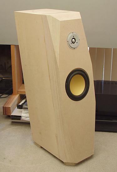
    For those that don't remember, Tibor's sealed design speaker, here's a pic.

    Image not available

    To date the 'best' ported version using the Hi-Vi drivers is Jon's M8a-T&A

    Click image for larger version  Name:	LivingRoomW_DrvrsSS.jpg Views:	97 Size:	48.5 KB ID:	929560

    Just so people don't get confused, either cabinet design will work for the MTM. The faceted design is optimal, but the standard flat front works VERY well.

    Later today Jon's going to post box and port sizes modeled in Unibox.

    The only 'fixed' cabinet dimensions are having a 12" wide front baffle, and maintaining the fixed front baffle spacing between the MTM drivers. This means that only the height and depth should be adjusted to create the required volume for good bass response.

    Here are the block diagrams of the MTM crossovers.

    Click image for larger version

Name:	M8MTMHP.jpg
Views:	110
Size:	104.4 KB
ID:	948242

    Click image for larger version

Name:	M80MTMLP.jpg
Views:	118
Size:	192.8 KB
ID:	948243

    Here's a link the Pete Mazz's ported version of this design..

    Link not available
    Last edited by theSven; 15 August 2023, 18:42 Tuesday. Reason: Update image location

    IB subwoofer FAQ page


    "Complicated equipment and light reflectors and various other items of hardware are enough, to my mind, to prevent the birdie from coming out." ...... Henri Cartier-Bresson
  • JonMarsh
    Mad Max Moderator
    • Aug 2000
    • 15304

    #2
    The M8ta is an "optimal" extension cabinet for a single M8 woofer; with a net volume of 68 liters it uses a flared 3" port, with a box tuning of 25 Hz; this results in a slight slope down from 100 Hz to 25 Hz anechoic, which will end up being pretty flat in room, considering LF room gain. Note that the port exits the bottom of the cabinet; in many regards, this system behaves like Martin Kings description of a ported 1/4 wave TL. The cabinet has about 3" clearance from the bottom surface to the floor, due to the tripod feet and heavy points about 1.5-2" long. Exiting to the floor also reduce the affect of port resonances in the midrange (~ 600 Hz). I normally recommend port exiting to the rear or the floor. In room a single cabinet is capable of ~100 dB down to 24 Hz, with higher output above 45 Hz. Maximum port velocity is about 5% of the speed of sound.

    Higher output in the 40-50Hz region is possible by using a smaller box, and shifting the box tuning up to 32 Hz or so, but then you wind up with the M8 MkIV cabinet design for the published two way article; box about 48 liters net internal volume. The sacrifice is low end extension for higher mid bass power handling.

    An optimal extension dual woofer cabinet design is going to be about twice the size; I'd suggest 125 liters net volume for two woofers. This will require a 4" ID port. Because of the larger box volume, the port length will still be only about 12 inches long for Fb of 25 Hz. This design will be down -3 dB from 100 Hz level at 26 Hz (anechoic), and maximum output from one box before including room gain will be >104 dB down to 23 Hz; in room, a stereo pair should be good for almost 110 dB down to 24 Hz. This is assuming 3 dB room gain (a conservative estimate; in some situations 6 dB is realized), and 3 dB from the second speaker. Note this assumes, as the previous design, a flared port, such as the PrecisionPort assemblies. These are well made and easy to work with, though I cut a smaller hole in the baffle and countersink route the baffle flare; this reduces the impact on port strength, but requires some care in assembly planning, as you can't put the port through the hole when fully assembled; I cement the back section from inside the cabinet with ABS cement after mounting the front in the baffle.

    Best regards,

    Jon


    Earth First!
    _______________________________
    We'll screw up the other planets later....
    the AudioWorx
    Natalie P
    M8ta
    Modula Neo DCC
    Modula MT XE
    Modula Xtreme
    Isiris
    Wavecor Ardent

    SMJ
    Minerva Monitor
    Calliope
    Ardent D

    In Development...
    Isiris Mk II updates- in final test stage!
    Obi-Wan
    Saint-Saƫns Symphonique/AKA SMJ-40
    Modula PWB
    Calliope CC Supreme
    Natalie P Ultra
    Natalie P Supreme
    Janus BP1 Sub


    Resistance is not futile, it is Volts divided by Amperes...
    Just ask Mr. Ohm....

    Comment

    • ThomasW
      Moderator Emeritus
      • Aug 2000
      • 10933

      #3
      I edited Jon's post and highlighted in blue the info that's specific to actually building the speaker. I didn't that info getting lost in the technical 'why' of the design.


      theAudioWorx
      Klone-Audio

      IB subwoofer FAQ page


      "Complicated equipment and light reflectors and various other items of hardware are enough, to my mind, to prevent the birdie from coming out." ...... Henri Cartier-Bresson

      Comment

      • Paul H
        Senior Member
        • Feb 2004
        • 904

        #4
        A few questions come to mind:

        The 12" required baffle width - is that dimension across the exposed front face of the speaker? ie If I'm going to cut a 3/4" radius roundoff on the two front vertical edges is the required cabinet overall width 13.5"?

        What are the MTM centre-centre layout dimensions?

        Is this very cheap capacitor something that can be used with some success? (cut/pasted from Solen.ca info for Bennic capacitor):
        GENERAL INFORMATION
        Type : Non-Polar Electrolytic Capacitor.
        Dielectric : Aluminum Oxide on Anode Foil.
        Construction : Round Tubular Type Metal Can, Axial Leads.
        Coating : Blue Plastic Tube Wrapped.
        Electrodes : Paper & Electrolyte on Cathode Foil.
        Leads : Tinned Pure Copper.

        TECHNICAL DATA
        Capacitance Range : 10 ... 330 ĀµF, E 12 series, Ā±10 %. (see specifications for details))
        Dielectric Constant : 7 er, polar dielectric.
        Dielectric Absortion Factor : Less than 5 % @ 20Ā° C.
        Equivalent Series Resistance : Low (see specifications for details)
        Self Inductance : Low
        Dissipation Factor : Low (see specifications for details)
        Temperature Range : -25Ā° C to +85Ā° C.
        Test Voltage : 1.5 x Vr for 2 sec.
        Rated Voltage : 100 VDC/63 VAC.
        Leads Diameter : 0.8, 1.0 mm. (see specifications for details)

        I ask about the cheap capacitors because, well, there's a lot on that xover schematic

        Thanks in advance,

        Paul

        Comment

        • ThomasW
          Moderator Emeritus
          • Aug 2000
          • 10933

          #5
          Hi Paul

          The baffle width is 12" total. You can round over the edges if you want to, but there's very little sonic benefit to doing that.

          We're familar with those caps, but sorry electrolytic caps should not be used.

          For your future reference, the wiring for the tweeter is as follows:

          Tweeter crossover >4 ohm variable L-pad > zobel network > tweeter

          Jon and I are both checking our hard drivers for the file with the MTM spacing. If we can't locate it, I'll just call Tibor and get him to take measurements off his baffles.

          FYI the little Radio Shack things are called European Terminals Note they sell 2 sizes of these be sure to get the size with the largest holes

          Image not available


          theAudioWorx
          Klone-Audio
          Last edited by theSven; 15 August 2023, 18:46 Tuesday. Reason: Remove broken image link and update urls

          IB subwoofer FAQ page


          "Complicated equipment and light reflectors and various other items of hardware are enough, to my mind, to prevent the birdie from coming out." ...... Henri Cartier-Bresson

          Comment

          • Paul H
            Senior Member
            • Feb 2004
            • 904

            #6
            Thanks, I thought the above capacitors were a no-go but figured I'd ask anyway. I guess I'll go with the massively-parallelled GE 10uf caps , unless the Solen "Fast Capacitors" (or other higher end capacitor) would make an audible difference, beyond the sound of another $100-$150US slipping out of my wallet! Any thoughts on that?

            I notice also that depending on the brand and type of capacitor, there is a 5-10% tolerance listed. Should those of us without testing equipment to verify actual capacitance worry about this?

            The round off on the front corners is simply for appearance - just my personal preference, which is of course one of the nice things about diy.

            Paul

            Comment

            • ThomasW
              Moderator Emeritus
              • Aug 2000
              • 10933

              #7
              Jon has used both the Solen and the GE caps. His opinion is that the GE are sonically as good as the Solens. Based on that, I've used the GEs for all the projects I've done in the last 4yrs.

              Other than that the benefit to using the Solen caps is that the crossover themselves will be physically smaller and quite a bit less work to assemble.

              The 10mdf $0.90/100pc GE caps are 10% tolerance. They are never higher than spec, they are always under. That saves the mfgr money.

              For hitting the cap value there are 2 options. One is to buy an LCR meter. I think PE, Radio Shack or MCM Elec has one that sells for ~$35-40US. Or I can measure the GE caps I have, and give you correction values. That will certainly get you within 5% or better. Let me know just before you place your Madisound order, and I'll tell you what extra values to buy.

              Here are the driver spacing dimensions. First note that the cabinets are mirror imaged, so adjust accordingly. We'll do the dimensions of the speaker on the right side of the picture posted above.

              The woofers are offset 1.75" to the left of the front baffle centerline. The woofer centers are 11.5" apart, that's center to center spacing between them.

              The tweeter is centered top to bottom between the woofers (so it's 5.75" below the top woofer and 5.75" above the bottom woofer). From the far right side of the baffle, the tweeter centerline is inset 3.5".

              Now regarding driver height. Set the height of the tweeter, so it's at or slightly below ear level. It's better to have the speakers tilted up slightly as opposed to need to tip them downward.

              Now you need to decide how you want to create the 125L net volume. The drivers occupy a total of 2L. The port occupies 1L. Figure 1L each for the 3 XO boards and internal bracing will also occupy space. So let's say a gross internal volume of ~130-132L

              Don't get all hung up in absolutes, there's roughly a 10% 'fudge' factor in the enclosure volume of ported designs. When possible we prefer to error on the 'too large' size. After the cabinet is built it's easier to shrink the internal volume than it is to stretch it

              If any of this isn't clear let me know.....


              theAudioWorx
              Klone-Audio

              IB subwoofer FAQ page


              "Complicated equipment and light reflectors and various other items of hardware are enough, to my mind, to prevent the birdie from coming out." ...... Henri Cartier-Bresson

              Comment

              • Tibor
                Member
                • Oct 2000
                • 66

                #8
                Holly Cow your building a MONSTER !!!
                Best of luck with your DIY speakers you will be very happy .
                I am also a fellow Canadian so hope your big and strong to move them .
                Tibor

                Comment

                • Paul H
                  Senior Member
                  • Feb 2004
                  • 904

                  #9
                  When I start sending sketches in here you'll be able to see the innocuous 12" trailer tires built in at the bottom It looks like they'll be well over 100 lbs, as I'll most likely be using MDF.

                  Some quick calcs and notes to share before I do some sketches of the box:

                  Firstly,

                  The 1.75" offset from centreline for the woofer doesn't work with my math - The woofer is 8.5" diameter, or 4.25" radius. If a 4.25" radius is offset 1.75" it ends up at 6" from centre, or right on the extreme edge of the 12" wide cabinet. So...

                  Is the distance from the right side of the woofer to the right cabinet edge 1.75" more than than left side of woofer to left edge? (That would be a 7/8" offset from centre and would fit) ...

                  Or .. am I still confused about baffle width vs front face of cabinet width - are they one and the same, or is the baffle width the clear interior side-side dimension?

                  Secondly,

                  I would plan to use 2 layers of 3/4" MDF for the front face. Would a single or double layer be normal/appropriate for the other sides/top/bottom? I know thicker is better, but how thick is thick enough?

                  Lastly, approximate overall dimensions will be 47Hx12Wx19D, based on 1.5" front face thickness and 3/4" elsewhere. That's not so big really ... it's not like the ones posted in the OMG! post in this forum now )

                  Paul

                  Comment

                  • ThomasW
                    Moderator Emeritus
                    • Aug 2000
                    • 10933

                    #10
                    Sorry about that, we built these 2+yrs ago, so my memory is a bit stale....

                    I just had Tibor measure his cabinets........

                    He said that the outside edge of the woofers are 1-1/4" in from one side, and 2-3/8" in from the other side. Now that adds up to 12.125. Factoring in that he started with a 12" width and then added layers of wood veneer on both sides. So we're pretty close to dead on using 1" of centerline offset..

                    I just found the original pdf for the M8a, it's 215mm in diameter vs the M8n which is 222mm in diameter. So we'll need to compensate for that difference. This should only impact the offset placement of the tweeter.

                    But lets wait on finalizing the MTM driver spacing until Jon and I can sit down with a baffle diffraction program and rerun the system. This should have no impact on you starting to build the boxes. The holes for the drivers are usually cut after the box has been assembled.

                    The 12" dimension is the total width of the outside front of the speaker.

                    Typically we use no less than 1.5" thick material for the entire cabinet. And we add interior bracing to that. It's very important that the cabinet doesn't vibrate. If weight is a issue (yes these will be HEAVY) make the inner layer out of ply.


                    theAudioWorx
                    Klone-Audio

                    IB subwoofer FAQ page


                    "Complicated equipment and light reflectors and various other items of hardware are enough, to my mind, to prevent the birdie from coming out." ...... Henri Cartier-Bresson

                    Comment

                    • ThomasW
                      Moderator Emeritus
                      • Aug 2000
                      • 10933

                      #11
                      When building a box I build the outer layer first, and leave a bottom, back or side open. Then I do the driver cutouts. Then I laminate the inner layer in sections.

                      I use the sections instead of dados to separate the cross-section stiffening braces. Here's an example of that technique

                      Image not availalbe

                      Now of course the bracing for your MTMs don't need to be this extreme.

                      For Tibor's we used a pair of full cross-section mdf braces with cutouts in them. The first was placed behind the tweeter. The second was lower, I don't remember the exact placement.

                      In the pic below (top of box was open at this point) the first inner layers have been installed and the (upper) cross-section brace has been installed. On the right side if the pic you can see where the first piece of the next inner layer has been placed.

                      Image not availalbe

                      In this pic below you can see the two mdf cross-section braces, and if you look carefully you can see the 2"X4"s we used as side to side braces, these are mounted one behind each woofer.

                      Image not availalbe

                      I'll detail this sandwich layering tech.

                      We cut full sized pieces that would create the inner box. Then we cut a section off from each of the 4 inner pieces that were a length that corresponded with where the 1st brace was to be placed. Those pieces were attached inside the box with glue and brad nails. Then we dropped in the first brace. It to was glued and nailed in place.

                      Next we cut off the next layer. The length of these of course corresponded to where the next brace was to be placed. Those pieces were glued and nailed in, then the next brace was installed.

                      Here's a shot of of one of the cross-section braces. The cutouts were sized so that there was 2" of mdf left on every edge. The reason it doesn't look 2" wide on the outer margins, is of course because it's covered by the inner box pieces.

                      Image not availalbe

                      I suppose this is about as clear as mud?????

                      Edit to fix links


                      theAudioWorx
                      Klone-Audio
                      Last edited by theSven; 11 March 2023, 13:22 Saturday. Reason: Update image location

                      IB subwoofer FAQ page


                      "Complicated equipment and light reflectors and various other items of hardware are enough, to my mind, to prevent the birdie from coming out." ...... Henri Cartier-Bresson

                      Comment

                      • Paul H
                        Senior Member
                        • Feb 2004
                        • 904

                        #12
                        I checked my moving dolly and it's good for over 300 lbs, so we're fine with the double mdf

                        The layering technique was described very well and makes sense to me, except why go this route rather than double-layering all panels first and then dadoing for cross-bracing?

                        Also, does changing the type of cabinet (in this case to a ported) require tweaking of crossovers in any way?

                        I asked about capacitance measurement above without realizing that a good multimeter can do that. My 13 year old cheap meter died a couple of weeks ago - I'll make sure that its replacement can measure capacitance in the right ranges.

                        Paul

                        Comment

                        • Cdub
                          Member
                          • Aug 2003
                          • 56

                          #13
                          Thomas,

                          This sounds sounds like a great project!! It helps to have the floor space and a strong back too Having heard the M8 MkIV I am very interested. I was wondering if Tibor's version is a sealed MTM version correct? I think I read that the tuning on his version was 30hz, is this correct? Also I was wondering if you have any general listening impressions of the MTM vs. MkIV design. Is it mostly greater sensitivity and output?

                          On a side note the Arvo project looks incredible and I'm sure sounds better!

                          Jon,

                          When are you going to finish those naked M8ta's? They must be getting cold with no veneer on them :W I'm sure they'll sound even better then they look when they're done.

                          Keep up the great job on all the projects!! I love reading about your guys projects.

                          Chris

                          Comment

                          • ThomasW
                            Moderator Emeritus
                            • Aug 2000
                            • 10933

                            #14
                            Paul,

                            Nope no difference using dado's. I'm just lazy, with a bad back and usually don't have any 'helpers' around. So I find the layering method easier; since there a no 1.5" thick panels to build, move around, or machine.

                            Also I prefer to do the driver cutouts in the outer boxes with their 3/4" thinkness, than plunge through 1.5" thick material. After doing the outer layer cutouts, I cut the inner layer with a bearing-over router bit.

                            No, there aren't any differences between the crossovers for sealed or ported cabinets.


                            Chris,

                            Yep Tibor's are sealed. We never measured the actual tuning of Tibor's speakers. It wasn't an issue given his use of a sub.

                            The M8aMKIV are tuned to ~32Hz.

                            I've always preferred MTMs. I like both the dispersion, and the 'punch' that MTMs offer.


                            theAudioWorx
                            Klone-Audio

                            IB subwoofer FAQ page


                            "Complicated equipment and light reflectors and various other items of hardware are enough, to my mind, to prevent the birdie from coming out." ...... Henri Cartier-Bresson

                            Comment

                            • ThomasW
                              Moderator Emeritus
                              • Aug 2000
                              • 10933

                              #15
                              Paul,

                              Some more things to take into consideration.

                              The crossover boards are quite large. Something like 10"X15" or so. Usually XO boards are sized so that they will fit through the woofer holes, that's not possible with this design.

                              So you'll need to decide how you want to deal with the XO boards.

                              Tibor wanted to have the cabinets sitting on a plinth. We decided to make the plinth serve as a removable bottom for the cabinets. That way it was easy to insert and service the crossovers.

                              One of the pictures above (black & white wires dangling from it) shows the bottom view with all the bracing installed. There you'll see a 'frame' around the bottom of the box. The frame was made from some scrap hickory 2"X2"'s. Lag bolts were screwed up throught the bottom of the plinth and into the hickory. Sealed with a layer of closed cell foam tape, that gave us an air tight, but easily removable bottom.

                              I uploaded big pics of the assembled XO's. Someone (we can't say who,) had a mild alzheimers moment, so the wiring on the woofer and tweeter XO's have a couple of errors. Only use the pics as a layout reference for the raw components. Don't copy the point to point wiring as shown in the pics, use the block diagrams instead.

                              Note that the woofer and tweeter XO input/output terminals are wired differentlly compared to that of the zobel. This is for ease of construction. The woof/tweet boards are (+/-) input on the left side and (+/-) output on right side. The zobel has (+) input & output on the left side, and (-) input & output on the right side

                              Finally to make the large clusters of caps we use tinned copper wire that we double up twice, = 4 wires, that are then spun in a elec drill to make a thick tight bundle. You have a couple of options. RS sells raw copper antenna wire that's multi-stranded. It's the right gauge, it must be tinned with solder before attaching the caps. Or you can simply go to a home center store and by a few feet of solid copper AC ground wire. It to must be tinned before soldering on the caps

                              theAudioWorx
                              Klone-Audio
                              Last edited by ThomasW; 24 December 2008, 11:36 Wednesday.

                              IB subwoofer FAQ page


                              "Complicated equipment and light reflectors and various other items of hardware are enough, to my mind, to prevent the birdie from coming out." ...... Henri Cartier-Bresson

                              Comment

                              • Paul H
                                Senior Member
                                • Feb 2004
                                • 904

                                #16
                                I was actually thinking about how very large the crossover boards would need to be, and was leaning towards putting them on the back side of the cabinet, outside the sound portion of the speaker box, but covered of course with a separate removable panel.

                                The removable panel wouldn't need to be sound-tight in this case. One advantage of this approach is if I ever wanted to make changes or adjustments (ie to fix something I mess up during assembly that only becomes apparent to me when smoke starts rising) they're easy to access.

                                I'm going to do some sketches and check some measurements tonight to see if this can work in a speaker cabinet that won't look too awful.

                                Paul

                                Comment

                                • ThomasW
                                  Moderator Emeritus
                                  • Aug 2000
                                  • 10933

                                  #17
                                  I was hesitant to recommend them, but outboard XO's are really a nice way to go. Having the tweeter L-pad as an external component is quite convenient.

                                  You can decrease the internal box size by ~3L or so, and keep the XO's somewhat isolated from the internal pressure waves/vibrations.

                                  If you need to attach the XO boards vertically, use 2-BIG strips of either the marine or industrial Velcro. We use hot glue over top of the peel-n-stick adhesive. Use of Velcro further isolates the XO's from vibration.


                                  theAudioWorx
                                  Klone-Audio

                                  IB subwoofer FAQ page


                                  "Complicated equipment and light reflectors and various other items of hardware are enough, to my mind, to prevent the birdie from coming out." ...... Henri Cartier-Bresson

                                  Comment

                                  • JonMarsh
                                    Mad Max Moderator
                                    • Aug 2000
                                    • 15304

                                    #18
                                    Mounting the crossover boards external is a nice way to go if you're willing to go to the hassle. The original crossover boards were split into three boards, and they fit through the woofer hole, based on the width of the board, and the woofer hole cutout.

                                    In the X1 SLAM clones, the upper module had a section in the back which was seperated from the main cabinet, and open at the bottom, the Xover boards were mounted up in this. Something similar might work for you, but it would complicate the woodworking a bit.

                                    Regards,

                                    Jon

                                    Definitely an important thing to work out before you finalize your construction plan!


                                    Earth First!
                                    _______________________________
                                    We'll screw up the other planets later....
                                    the AudioWorx
                                    Natalie P
                                    M8ta
                                    Modula Neo DCC
                                    Modula MT XE
                                    Modula Xtreme
                                    Isiris
                                    Wavecor Ardent

                                    SMJ
                                    Minerva Monitor
                                    Calliope
                                    Ardent D

                                    In Development...
                                    Isiris Mk II updates- in final test stage!
                                    Obi-Wan
                                    Saint-Saƫns Symphonique/AKA SMJ-40
                                    Modula PWB
                                    Calliope CC Supreme
                                    Natalie P Ultra
                                    Natalie P Supreme
                                    Janus BP1 Sub


                                    Resistance is not futile, it is Volts divided by Amperes...
                                    Just ask Mr. Ohm....

                                    Comment

                                    • ThomasW
                                      Moderator Emeritus
                                      • Aug 2000
                                      • 10933

                                      #19
                                      The original crossover boards were split into three boards, and they fit through the woofer hole, based on the width of the board, and the woofer hole cutout.
                                      A mind is a terrible thing to have lost........... :sos:

                                      He's talking about the original M8aMKIV cabinets and their XO's, not the Tibor's MTM mini-towers


                                      theAudioWorx
                                      Klone-Audio

                                      IB subwoofer FAQ page


                                      "Complicated equipment and light reflectors and various other items of hardware are enough, to my mind, to prevent the birdie from coming out." ...... Henri Cartier-Bresson

                                      Comment

                                      • Paul H
                                        Senior Member
                                        • Feb 2004
                                        • 904

                                        #20
                                        I looked at and thought about a few options for speaker size and shape, but I came back to a rectangular box for various reasons.

                                        To get a volume of 128 L before deductions for drivers, bracing etc., using a 1.5" thick wall all round, I'm getting outside dimensions of 12"wide x 54" high x 20"deep.

                                        12" is the required baffle width to achieve certain acoustics, 54" is my own self-imposed approx. max height, and 20" comes out in the arithmetic.

                                        With this size, I'll go inboard with the x-overs, as I'd need at least another 3" depth to mount them at the back, and 20" is plenty deep.

                                        I'll use a removable bottom similar to Tibor's setup to mount the crossovers in the lower section and to be able to access them in the future.

                                        It looks like from the xover photos above that at least one of the resistors 'ain't quite right'.

                                        I also notice on closer examination of schematics that tweeter is supposed to be hooked up with +- reversed?

                                        Paul

                                        Comment

                                        • ThomasW
                                          Moderator Emeritus
                                          • Aug 2000
                                          • 10933

                                          #21
                                          It looks like from the xover photos above that at least one of the resistors 'ain't quite right'.
                                          There are more problems than that. Use the wiring on the schematics it's correct.
                                          I also notice on closer examination of schematics that tweeter is supposed to be hooked up with +- reversed?
                                          This is confusing, but no the tweeters aren't reversed.

                                          The zobel board in/out terminal is wired different from the woofer/tweeter board terminals. The zobel board terminal is wired as follows, from left to right
                                          + in (1B), - out(2B), + out(3B), - in(4B)

                                          Remember the high frequency circuit is wired as follows;

                                          Tweeter crossover board > 4 ohm variable L-pad > zobel network board > tweeter


                                          theAudioWorx
                                          Klone-Audio

                                          IB subwoofer FAQ page


                                          "Complicated equipment and light reflectors and various other items of hardware are enough, to my mind, to prevent the birdie from coming out." ...... Henri Cartier-Bresson

                                          Comment

                                          • Paul H
                                            Senior Member
                                            • Feb 2004
                                            • 904

                                            #22
                                            A question regarding inductors - what gauge wire would you suggest?

                                            If it doesn't much matter, the 18 or 20 ga is significantly cheaper than the 14 or 16ga.

                                            Thanks,

                                            Paul

                                            Comment

                                            • JonMarsh
                                              Mad Max Moderator
                                              • Aug 2000
                                              • 15304

                                              #23
                                              The inductors which are used in the LCR zobel for the tweeter can be high resistnace, small guage, as long as the resitor value is adjusted to compensate for the increase in DCR.

                                              The series inductors for the woofers are critical, due to the potential power loss and affect on damping factor. We use AWG14 or AWG15. This is important for the single driver two way, even more so for the MTM, becuase woofers in parallel are four ohm load, and if you had a series inductor with one or two ohms DCR, from 15 to 25% of the power would be dissipated (lost) in the inductor. You don't want that, trust me! :E

                                              You should see the inductors on the bottom end of the Arvo Part passive crossover- AWG 12! :banana:

                                              The tweeter shunt inductors are also important because of the LF roll off, to keep the lows continuing to roll off with decreasing frequency into the tweeter. I don't recommend cutting corners their, either. Again, AWG14 or 15 is what we usually use.

                                              Best regards,

                                              Jon


                                              Earth First!
                                              _______________________________
                                              We'll screw up the other planets later....
                                              the AudioWorx
                                              Natalie P
                                              M8ta
                                              Modula Neo DCC
                                              Modula MT XE
                                              Modula Xtreme
                                              Isiris
                                              Wavecor Ardent

                                              SMJ
                                              Minerva Monitor
                                              Calliope
                                              Ardent D

                                              In Development...
                                              Isiris Mk II updates- in final test stage!
                                              Obi-Wan
                                              Saint-Saƫns Symphonique/AKA SMJ-40
                                              Modula PWB
                                              Calliope CC Supreme
                                              Natalie P Ultra
                                              Natalie P Supreme
                                              Janus BP1 Sub


                                              Resistance is not futile, it is Volts divided by Amperes...
                                              Just ask Mr. Ohm....

                                              Comment

                                              • Paul H
                                                Senior Member
                                                • Feb 2004
                                                • 904

                                                #24
                                                There's one inductor per speaker in series for the woofers, a 0.90 mH which I'll order as a 14ga.

                                                The rest I'll probably go with 16ga, as the differences in DCR from 14 to 16ga are less than 0.1 Ohms (ie .27mH has DCR of 0.15Ohms w/16ga and 0.10 w/14ga), and it appears the laws of diminishing returns may be kicking in. It's about an extra $50 to go all 14ga. These are Solen standard inductors, incidentally.

                                                If I'm missing something, (ie if that .05 Ohms difference is really important) just give me a 'virtual kick'. I'm leary of victimizing myself with the 'a little knowledge is dangerous' syndrome

                                                Paul

                                                Comment

                                                • ThomasW
                                                  Moderator Emeritus
                                                  • Aug 2000
                                                  • 10933

                                                  #25
                                                  It's not just the changes on the resistance. It's also the power handling. That's why we really recommend using the 14 gauge.

                                                  You certainly don't want to change the 0.90 or 0.45 in the woofer circuit. These carry a ton of power and need to be 14 gauge

                                                  The 0.70 in the zobel could be 16 gauge. However if it's resistance is higher than the 14 gauge (that's what we use for the computer models), then the resistor values in the zobel must be adjusted to reflect the change in the inductor. All this stuff is interrelated so changing one thing impacts others....

                                                  For the tweeter, if the 16 gauge 0.27 and 0.8 are as little as .05 difference in resistance compared to the 14 gauge then that's acceptable.


                                                  theAudioWorx
                                                  Klone-Audio

                                                  IB subwoofer FAQ page


                                                  "Complicated equipment and light reflectors and various other items of hardware are enough, to my mind, to prevent the birdie from coming out." ...... Henri Cartier-Bresson

                                                  Comment

                                                  • Paul H
                                                    Senior Member
                                                    • Feb 2004
                                                    • 904

                                                    #26
                                                    Thomas and Jon,

                                                    Thanks (again),

                                                    I just sent off requests for pricing confirmation with a detailed materials list, including 14ga inductors all round.

                                                    Paul

                                                    Comment

                                                    • Paul H
                                                      Senior Member
                                                      • Feb 2004
                                                      • 904

                                                      #27
                                                      Well I was keen on jumping into this speakers right away, but the M8N woofers are out of stock at PE and not expected in until mid-March. The Swan website lists PE as the sole North American distributor. I'd kinda like to have them ordered and be confident I'm getting them before spending a bunch of other time and money on the rest of the parts.

                                                      I guess for the moment I'll finish up the cabinet plans, and then wait as fast as I can..

                                                      Paul

                                                      Comment

                                                      • JonMarsh
                                                        Mad Max Moderator
                                                        • Aug 2000
                                                        • 15304

                                                        #28
                                                        I can appreciate the feeling and frustration- I'm waiting for Titanic MkIIs (10") to be back in stock at PE also, for my current project. There's an alternative woofer I probably could use, but it would require new baffles and a major crossover mod.

                                                        ~Jon


                                                        Earth First!
                                                        _______________________________
                                                        We'll screw up the other planets later....
                                                        the AudioWorx
                                                        Natalie P
                                                        M8ta
                                                        Modula Neo DCC
                                                        Modula MT XE
                                                        Modula Xtreme
                                                        Isiris
                                                        Wavecor Ardent

                                                        SMJ
                                                        Minerva Monitor
                                                        Calliope
                                                        Ardent D

                                                        In Development...
                                                        Isiris Mk II updates- in final test stage!
                                                        Obi-Wan
                                                        Saint-Saƫns Symphonique/AKA SMJ-40
                                                        Modula PWB
                                                        Calliope CC Supreme
                                                        Natalie P Ultra
                                                        Natalie P Supreme
                                                        Janus BP1 Sub


                                                        Resistance is not futile, it is Volts divided by Amperes...
                                                        Just ask Mr. Ohm....

                                                        Comment

                                                        • Lloyd E
                                                          Junior Member
                                                          • Feb 2004
                                                          • 10

                                                          #29
                                                          ThomasW,

                                                          I had read in another forum that you had also developed a center channel using the same drivers and XO. I am very interested in building the MTM towers and center as the front stage for my theater. Just curious to the vitals (volumn, dimensional constraints, etc.) for the center channel, I downloaded the jpegs of the XO's but, I could not locate any specs for the center channel.

                                                          Regarding the towers, if I decide to go sealed, would the volumn change from the 125L for ported? As I could not find the volumn for Tibor's speakers in the thread. I have an SVS sub, so I am not concerned with a full range speaker.

                                                          I have also read various things regarding the effects of laying an MTM design on its side. Does the offset of the tweeter help to compensate for this phenomena? Do you have a 3-way design in the works to help for an increase in sound stage height?

                                                          Thanks for your help!

                                                          Comment

                                                          • ThomasW
                                                            Moderator Emeritus
                                                            • Aug 2000
                                                            • 10933

                                                            #30
                                                            Hi Loyd,

                                                            Here's info on the 2-way MTM center

                                                            The XO and baffle design is for either mains or a center. When we first designed Tibor's system it was a given that he'd need a center, so this was taken into account.

                                                            Primary trick to creating any MTM center is having an offset tweeter. Know I know some of the kit retailers don't do that, but it makes a big difference. Note that it doesn't matter if the tweeter is offset to the top or bottom. You can try it either way, and chose whichever you prefer.

                                                            You can make a center as large or small as is needed. Tibor's was 32" long that just fit in his entertainment center. We built his box sealed since the box size was to small 12" X 32" X 20"? I think?. If you're going to go with a bigger box then it could be ported, but for all intents and puroses that's added work for not much benefit.

                                                            Start by marking a centerline on the width of the baffle. That's where the tweeter will go. On the M8a we inset it 3.75". Given that the M8ns are bigger than the M8as. The amount of tweeter offset shoud be such that there's a 1/4" or so of wood between the edge of the woofer and tweeter mounting flanges.

                                                            MTM spacing is as follows the woofers are aligned 1" off-center on a 12" wide baffle. The center to center spacing for the woofers is 11.5".

                                                            We'll be making a 3-way center using the Arvo design. So a vertical MTM stack with woofers on either side. Info on that design won't be available until the end of March, when Jon returns to Denver for his next visit.....


                                                            theAudioWorx
                                                            Klone-Audio

                                                            IB subwoofer FAQ page


                                                            "Complicated equipment and light reflectors and various other items of hardware are enough, to my mind, to prevent the birdie from coming out." ...... Henri Cartier-Bresson

                                                            Comment

                                                            • Lloyd E
                                                              Junior Member
                                                              • Feb 2004
                                                              • 10

                                                              #31
                                                              ThomasW,

                                                              Thanks for the great information. Looks like I will have something to work on during the spring and summer! I might hold out for the 3 way design since I am on my own schedule. I built the Audax HT kit for my father and I liked the 3-way center. As stated earlier, the M8n's are on backorder at PE until mid March... so no rush for me.

                                                              What are your thoughts for having the main's front baffle being tilted back something like 7 degrees? Would that create a problem on the timing of the two mids? The tower would be shaped like a parallelogram.

                                                              One more quick question, regarding the XO's. On the diagram, C1031 is 8u75? Is that supposed to be 8.75 uF? I looked at the pictures and that seemed to be the value on that grouping of caps. Just a little confused as it also appeared to have 2.99 in the same assembly.

                                                              Thanks again!
                                                              Lloyd

                                                              Comment

                                                              • Paul H
                                                                Senior Member
                                                                • Feb 2004
                                                                • 904

                                                                #32
                                                                We got a little over a foot of snow from midnight to 7AM, another foot to fall today by 7-8PM, and 60MPH winds .. so I have a little time at home to work out speaker box configurations.

                                                                What I'm getting is a box with outside dimensions of 12" wide x 22.5" deep x 46" high, with a net volume of 124L, after deductions for drivers, bracing and 1.5" thick sides all round.

                                                                I'm going to put this on a pedestal 6" high x 16" wide x 26.5" deep (2" wider than speaker box all round)(overall height 52"), with the intent of mounting the crossovers on a single board that fits inside the pedestal. The pedestal should have a clear interior space of 4" high x 13" wide x 23" deep for the xovers. I'll likely use solen or other capacitors (rather than parallelling the much cheaper GE capacitors from Madisound) to save space and fit the crossovers within the pedestal.

                                                                The vent will go out through the back, say an inch up from the bottom of the speaker cabinet.

                                                                Tweeter height will be approximately 36" above the floor, ear height for our couches and chairs.

                                                                Binding posts will be mounted on the back of the pedestal.

                                                                I considered winding the inductors myself, but 14ga magnet wire is pretty well impossible to find around here.

                                                                Any recommendations for insulation inside the cabinet, or is it a trial and error method to get the right thickness and configuration?


                                                                Paul

                                                                Comment

                                                                • JonMarsh
                                                                  Mad Max Moderator
                                                                  • Aug 2000
                                                                  • 15304

                                                                  #33
                                                                  Regarding internal insulation and damping, I've either used heavy felt or Whispermat to line the side and back walls, then a "bolus" of folded up dacron/polyester batting as used for quilting fill (i.e., it's in a sort of sheet like form about 1" thick) behind the woofer, about 6" deep, covering the woofer area. DON'T put damping materials like the polyester fill near the flared port entry. Fiber glass would be OK, too, but it's a little nastier to work with. The goal is to dampen the midrange reflections behind the woofers, but not to overdamp the box/port system in the low frequencies. This "stuffing" approach will produce a bass response that has a gadual decreases from 100 Hz on down to the box tuning, and tightens up the perceived transient response, while still reducing driver excursion in the low end. The slight roll off is complemented by the room gain, so the net effect (once the speaker is properly placed) should be pretty flat. The AudioXpress article goes into some detail about LF effects and room placement, in the first part (of 3).

                                                                  Best regards,

                                                                  Jon


                                                                  Earth First!
                                                                  _______________________________
                                                                  We'll screw up the other planets later....
                                                                  the AudioWorx
                                                                  Natalie P
                                                                  M8ta
                                                                  Modula Neo DCC
                                                                  Modula MT XE
                                                                  Modula Xtreme
                                                                  Isiris
                                                                  Wavecor Ardent

                                                                  SMJ
                                                                  Minerva Monitor
                                                                  Calliope
                                                                  Ardent D

                                                                  In Development...
                                                                  Isiris Mk II updates- in final test stage!
                                                                  Obi-Wan
                                                                  Saint-Saƫns Symphonique/AKA SMJ-40
                                                                  Modula PWB
                                                                  Calliope CC Supreme
                                                                  Natalie P Ultra
                                                                  Natalie P Supreme
                                                                  Janus BP1 Sub


                                                                  Resistance is not futile, it is Volts divided by Amperes...
                                                                  Just ask Mr. Ohm....

                                                                  Comment

                                                                  • ThomasW
                                                                    Moderator Emeritus
                                                                    • Aug 2000
                                                                    • 10933

                                                                    #34
                                                                    Lloyd

                                                                    Yes 8u75 is the univeral notation for a 8.75 mfd cap.

                                                                    Sorry but I can't locate any 2.99 value anywhere on any of the drawings.

                                                                    Parallelogram is fine. Building it should be fun....

                                                                    Paul,

                                                                    Trying to wind coils by hand is a mightmare. It's almost impossible to get the turns applied evenly with equal tension

                                                                    We have a dedicated power winder with an automatic stop turncounter. Even with this, winding BIG 14 gauge inductors is no picnic. Both Jon and I have the blisters to prove it.


                                                                    theAudioWorx
                                                                    Klone-Audio

                                                                    IB subwoofer FAQ page


                                                                    "Complicated equipment and light reflectors and various other items of hardware are enough, to my mind, to prevent the birdie from coming out." ...... Henri Cartier-Bresson

                                                                    Comment

                                                                    • Lloyd E
                                                                      Junior Member
                                                                      • Feb 2004
                                                                      • 10

                                                                      #35
                                                                      ThomasW,

                                                                      Thanks. I guess I was unclear on the 2.99 thing, I looked at the pictures of the XO's and saw 2.99 and 8.75 written on the same capacitor grouping. You are correct in that 2.99 does not appear on any of the drawings.

                                                                      I will send pictures should I decide go with a parallelogram shape. I am insprired by the Usher Dancer series (http://www.usheraudio.com/speaker-ac20.html) for the look . Going with a tilt back and curved side will probably be out of my woodworking skills. I had considered the Usher 2-way kits, but I have read tremendous reviews about your collaborated design and wanted to give it a try.

                                                                      Comment

                                                                      • Lloyd E
                                                                        Junior Member
                                                                        • Feb 2004
                                                                        • 10

                                                                        #36
                                                                        ThomasW,

                                                                        Thanks. I guess I was unclear on the 2.99 thing, I looked at the pictures of the XO's and saw 2.99 and 8.75 written on the same capacitor grouping. You are correct in that 2.99 does not appear on any of the drawings.

                                                                        I will send pictures should I decide go with a parallelogram shape. I am insprired by the Usher Dancer series (http://www.usheraudio.com/speaker-ac20.html) for the look . Going with a tilt back and curved side will probably be out of my woodworking skills. I had considered the Usher 2-way kits, but I have read tremendous reviews about your collaborated design and wanted to give it a try.

                                                                        Comment

                                                                        • ThomasW
                                                                          Moderator Emeritus
                                                                          • Aug 2000
                                                                          • 10933

                                                                          #37
                                                                          Lloyd,

                                                                          As a longtime subscriber to AudioXpress I'm familar with the Usher design. They're WAY cool looking.............

                                                                          Use the XO pictures only as a large part layout reference. There are wiring mistakes in 2 of the 3 boards (primarily resistors and jumpers). We were in such a rush after fixing the errors, that no pictures were taken of the correctly wired boards. Note that the wiring schematics are correct


                                                                          theAudioWorx
                                                                          Klone-Audio

                                                                          IB subwoofer FAQ page


                                                                          "Complicated equipment and light reflectors and various other items of hardware are enough, to my mind, to prevent the birdie from coming out." ...... Henri Cartier-Bresson

                                                                          Comment

                                                                          • Paul H
                                                                            Senior Member
                                                                            • Feb 2004
                                                                            • 904

                                                                            #38
                                                                            I don't believe anyone's built these MTM's in a ported enclosure yet, so this is a very hypothetical question, more even than others I've posted here

                                                                            Is there a particular cause for concern that these ported speakers will be exceedingly difficult to tune, so they don't sound 'loose' or 'boomy', as compared to the probably tighter sounding sealed speakers?

                                                                            Paul

                                                                            Comment

                                                                            • ThomasW
                                                                              Moderator Emeritus
                                                                              • Aug 2000
                                                                              • 10933

                                                                              #39
                                                                              Given my fixation with the quality of IB bass, you don't think we'd design a speaker that booms?

                                                                              We like our bass 'tight', and well defined. We hope you do to...

                                                                              Boom can be a function of a mistuned box, bad baffle step compensation, and or more likely, interaction with the room due to poor placement. We've got the box tuning and baffle step compensation nailed, the room placement is up to you ...... 8)

                                                                              Note that all the original M8aMKI-MKIV designs were ported. So scaling up to a pair of drivers vs a single one isn't a problem.


                                                                              theAudioWorx
                                                                              Klone-Audio

                                                                              IB subwoofer FAQ page


                                                                              "Complicated equipment and light reflectors and various other items of hardware are enough, to my mind, to prevent the birdie from coming out." ...... Henri Cartier-Bresson

                                                                              Comment

                                                                              • JonMarsh
                                                                                Mad Max Moderator
                                                                                • Aug 2000
                                                                                • 15304

                                                                                #40
                                                                                This is why the box is tuned relatively low in these designs (32 Hz in the bookshelf, 25-27 Hz in the tower, and some damping material is used behind each driver. This results in smooth extension with a slight downward shelving if measured anechoicly, but fairly flat in room response. These are designe with baffle step compensation and low end suitable for placement away from the walls; put these a foot from the back wall, and they may be heavier than you like (though some like them that way). When speakers are placed too close to the wall, you have more issues with room interaction and irregular midbass/midrange. Read the Part 1 of the Audio Xpress article for detailed explanation. The overall voicing and room setup is pretty similar to Avalon speakers, for example- there's reasons for that. Many reasons.

                                                                                We have also done designs tuned for wall placement, like Thomas's bedroom version. Then baffle step comp is taken out completely. This affects a number of component values; it's not something that you must modify one part, so be sure you know what you want. Porting can still be OK for wall mount, but obviously not out the rear!


                                                                                ~Jon

                                                                                Best regards,


                                                                                Earth First!
                                                                                _______________________________
                                                                                We'll screw up the other planets later....
                                                                                the AudioWorx
                                                                                Natalie P
                                                                                M8ta
                                                                                Modula Neo DCC
                                                                                Modula MT XE
                                                                                Modula Xtreme
                                                                                Isiris
                                                                                Wavecor Ardent

                                                                                SMJ
                                                                                Minerva Monitor
                                                                                Calliope
                                                                                Ardent D

                                                                                In Development...
                                                                                Isiris Mk II updates- in final test stage!
                                                                                Obi-Wan
                                                                                Saint-Saƫns Symphonique/AKA SMJ-40
                                                                                Modula PWB
                                                                                Calliope CC Supreme
                                                                                Natalie P Ultra
                                                                                Natalie P Supreme
                                                                                Janus BP1 Sub


                                                                                Resistance is not futile, it is Volts divided by Amperes...
                                                                                Just ask Mr. Ohm....

                                                                                Comment

                                                                                • Paul H
                                                                                  Senior Member
                                                                                  • Feb 2004
                                                                                  • 904

                                                                                  #41
                                                                                  Thanks again gentlemen for your comments and explanation. I don't have those audioxpress articles but I should get them on order.

                                                                                  And now I need to get some rest .. 30" of snow in 24 hours .. got some serious snow clearing to do in the morning. Is clearing out a 100' driveway with 4' drifts an example of "slow work takes time"?

                                                                                  Paul

                                                                                  Comment

                                                                                  • Paul H
                                                                                    Senior Member
                                                                                    • Feb 2004
                                                                                    • 904

                                                                                    #42
                                                                                    I was thinking about this porting again ..

                                                                                    I do have a decent sized room, with space to put a large set of speakers. It's about 30' x 17'. However, the Wife Acceptance Factor for these speakers drops in proportion to the distance the speakers are located from the wall. I understand that these speakers shouldn't be placed against the wall, and I will be locating them for best sound.

                                                                                    My understanding is that a down-ported speaker is not quite as susceptible to problems with being placed relatively closer to the wall, compared to a rear-ported, so I should probably port them through the bottom.

                                                                                    Questions:
                                                                                    Does the above make sense?
                                                                                    How much clearance is recommended underneath the speaker with a port in the bottom? (carpeted floor, if it matters)

                                                                                    Paul

                                                                                    Comment

                                                                                    • JonMarsh
                                                                                      Mad Max Moderator
                                                                                      • Aug 2000
                                                                                      • 15304

                                                                                      #43
                                                                                      Hi Paul,

                                                                                      My understanding is that a down-ported speaker is not quite as susceptible to problems with being placed relatively closer to the wall, compared to a rear-ported, so I should probably port them through the bottom.
                                                                                      Let's think about this a little bit. What we're talking about with regards to walls or floor is acoustical boundary- i.e., a surface plane which causes the radiation to convert from full space to half space, and hence increasing the output by a theoretical 6 dB. I say theoretical, because walls and floors flex, which reduces the effective reflection. Sometimes boundary gain may reduce to 4 or 5 dB. Overall, there's little difference between a wall and a floor...

                                                                                      The bass reflex port makes a meaningful contribution to the speaker output over a range little over one octave, from about 25-30 Hz up to 60-65 Hz. Look at this plot of an M8 MkIV for the woofer and port contributions. The expected null in the driver output at port tuning frequency is not so large, because of the damping used to lower the cabinet and tuning Q. This makes for tighter bass (perceptually), but reduces the port output somewhat. The summed response, not shown, is a smooth but shallow downtilt from 100 Hz to the box tuning, than a faster roll off below that.


                                                                                      Click image for larger version

Name:	LF-NFPortSS.jpg
Views:	154
Size:	55.4 KB
ID:	929562


                                                                                      Both the woofer and the driver make significant LF output contributions. If they are co-located fairly close together (even on opposite sides of a 14" deep box), for analytical purposes in the below 65 Hz region they can be considered a single source.

                                                                                      Let's see what happens when we move that source around in respect to the three closest boundaries- floor, rear wall, and side wall.

                                                                                      In the 80's I prepared a MathCAD document for doing wave analysis of the room boundary response and the net in room frequency response for the speaker; this calculation modeled the nearfield LF response as an appropriate high pass filter function (sealed box 2nd order, Q=?; ported box 4th order, Q=?), and ignoring for the moment room modal effects and listener position, this provides a good starting analysis for in room response. It's sort of the fundamentals, you might say, for a monopole source, upon which all else builds. If you screw up this part, no amount of additional room treatments or listener positioning will fix it. This same sort of analysis is available in many modern speaker software program, like LSPCAD box mode, and Sound Easy.


                                                                                      This first example is a pretty typical setup, something my duaghter (bless her) might do, just because it's "convenient". One meter from the floor, 1.1 meter from the side wall, and 0.8 meter from the rear wall. Ugh. The magenta curve is the anechoic LF system response, the green curve is the room boundary resopnse, and the blue curve is the net result. Gee, that would probably sound like something of a boom box, wouldn't it, and the upper bass range on standup bass would really take a hit, as well as the low range of male vocals, and for cello, etc. Plus piano lower registers. So, it would sound both boomy and thin.

                                                                                      Click image for larger version

Name:	EP1-BoundaryGraphicSS.jpg
Views:	161
Size:	66.5 KB
ID:	929563


                                                                                      What do we have next? In this example, my daughter decided she didn't like the speakers out almost three feet from the wall, and so pushed them back so that the effective LF source is only about 18" from the wall. It's a little smoother in some regards, not quite as big an LF bump, but still some significant dips at 100 Hz, and a new one at 300 Hz. Sorry, I'll pass.

                                                                                      Click image for larger version

Name:	EP2-BoundaryGraphicSS.jpg
Views:	128
Size:	65.0 KB
ID:	929564


                                                                                      This last one is the M8 two way 8" system "bookshelf" on stands, with golden mean distances from boundaries tuned to complement the anechoic system response for optimized in room response. 1.21 meters from the side walls, about 2 meters from the rear walls. Distance from floor is determined by stands.

                                                                                      Click image for larger version

Name:	EP3PortedBoundaryGraphic1SS.jpg
Views:	152
Size:	64.4 KB
ID:	929565


                                                                                      Image not availalbe


                                                                                      As long as you have monopole LF sources in a room (box with boundaries, at it's simplest) you will have these effects. If one ignores them, you'll suffer the inevitable consequences of Father Physics.

                                                                                      Avalon Acoustics uses these same guidelines for ownders to setup their speakers; so do many other high end conventional speaker manufacturers. Cardas has on their site similar guidelines regarding the use of golden mean distances for speaker placement.

                                                                                      The only way to get around this and have somewhat improved placement flexibility is to use a dipole design; but you still have to have some rear wall distance, it's just that the side wall stuff and floor boundary distance issues pretty much go away.

                                                                                      Image not availalbe


                                                                                      Best regards,

                                                                                      Jon


                                                                                      Earth First!
                                                                                      _______________________________
                                                                                      We'll screw up the other planets later....
                                                                                      Last edited by theSven; 11 March 2023, 13:25 Saturday. Reason: Update image location
                                                                                      the AudioWorx
                                                                                      Natalie P
                                                                                      M8ta
                                                                                      Modula Neo DCC
                                                                                      Modula MT XE
                                                                                      Modula Xtreme
                                                                                      Isiris
                                                                                      Wavecor Ardent

                                                                                      SMJ
                                                                                      Minerva Monitor
                                                                                      Calliope
                                                                                      Ardent D

                                                                                      In Development...
                                                                                      Isiris Mk II updates- in final test stage!
                                                                                      Obi-Wan
                                                                                      Saint-Saƫns Symphonique/AKA SMJ-40
                                                                                      Modula PWB
                                                                                      Calliope CC Supreme
                                                                                      Natalie P Ultra
                                                                                      Natalie P Supreme
                                                                                      Janus BP1 Sub


                                                                                      Resistance is not futile, it is Volts divided by Amperes...
                                                                                      Just ask Mr. Ohm....

                                                                                      Comment

                                                                                      • Paul H
                                                                                        Senior Member
                                                                                        • Feb 2004
                                                                                        • 904

                                                                                        #44
                                                                                        Another question - which could be a separate post as it could relate to any type of DIY speakers ...

                                                                                        Suppose we start with very well thought out speaker design, carefully selected components, and reasonably competent assembly of these components
                                                                                        But
                                                                                        We don't test the actual drivers being used, instead relying on previous tests of other samples of the same type of driver (or manufacturer's data), and we don't measure capacitors and inductors but rely on the plus or minus 5% values provided (or use a cheap meter with a +-5% accuracy).

                                                                                        Would this type of parts tolerance produce a good speaker or a disaster?

                                                                                        To rephrase this question, what type of test equipment is required to ensure a good construction and assembly given a good design?

                                                                                        Paul

                                                                                        Comment

                                                                                        • ThomasW
                                                                                          Moderator Emeritus
                                                                                          • Aug 2000
                                                                                          • 10933

                                                                                          #45
                                                                                          Yeap there's little point in testing a +/-5% part with a +/-5% meter.

                                                                                          Actually except for ego purposes 5% parts are a very acceptable tolerance. I doubt that my ears are matched that closely

                                                                                          And from a practical standpoint differences in the speaker's location in the room, will probably account for a greater difference than the variation in the tolerance of the components.


                                                                                          theAudioWorx
                                                                                          Klone-Audio

                                                                                          IB subwoofer FAQ page


                                                                                          "Complicated equipment and light reflectors and various other items of hardware are enough, to my mind, to prevent the birdie from coming out." ...... Henri Cartier-Bresson

                                                                                          Comment

                                                                                          Working...
                                                                                          Searching...Please wait.
                                                                                          An unexpected error was returned: 'Your submission could not be processed because you have logged in since the previous page was loaded.

                                                                                          Please push the back button and reload the previous window.'
                                                                                          An unexpected error was returned: 'Your submission could not be processed because the token has expired.

                                                                                          Please push the back button and reload the previous window.'
                                                                                          An internal error has occurred and the module cannot be displayed.
                                                                                          There are no results that meet this criteria.
                                                                                          Search Result for "|||"