JL 10w3v3 home subwoofer

Collapse
This topic is closed.
X
X
 
  • Time
  • Show
Clear All
new posts
  • Brak
    Junior Member
    • Oct 2012
    • 3

    JL 10w3v3 home subwoofer

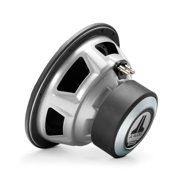
    Hi, I would like to build my own subwoofer for home theater and I can't seem to figure out the size of the cabinet I need to build. Using a JL 10w3v3 and a stealth acoustics 255r mono amp (450rms @4ohms) thanks
  • JonMarsh
    Mad Max Moderator
    • Aug 2000
    • 15297

    #2
    The JL driver is intended for car audio- witness it's 2 ohm VC impedance, which is commonplace in car systems, due to low driving voltage available, but not normally used in home audio systems.

    To figure out box alignments on your own, you would need to use the T/S parameters and and a calculation program such as Unibox (runs in Excel, free) or one of the standalone programs for bass system calculation or a program like LspCAD which also does this type of calculation. There are recommendations for the box size at Crutchfield, for sealed and ported, but with no port recommendation; I'd take these with a grain of salt, as the automotive cabinet gain for low frequencies is quite different from what happens in a typical room- the ported cabinet recommendation of 1.25 cu ft is what I'd start at for a sealed alignment. You can get more complete T/S parameters at the JL audio site. Google is your friend...


    W3v3 10-inch Subwoofer (500 W, 4 Ω)   This acclaimed Subwoofer strikes an outstanding balance in power handling, enclosure requirements and excursion to deliver excellent results in medium power applications. Several exclusive JL Audio technologies and proprietary assembly techniques are applied to the 10W3v3 to enhance linearity and reliability. The 10W3v3-4 is best used with amplifier power in the 150W - 500W range and is optimized to operate in a compact 0.625 cu. ft. (17.7 l) sealed enclosure, or a 1.125 cu. ft. (31.9 l) ported enclosure. Detailed enclosure recommendations can be found in the "Specifications" tab. Continuous Power Handling (RMS) 500 W Recommended Amplifier Power (RMS) 150 - 500 W Nominal Impedance (Znom) 4 Ω Nominal Diameter 10.0 in / 250 mm Overall Diameter (A) 10.5 in / 267 mm Mounting Hole Diameter (B) 9.0625 in / 230 mm Bolt Hole Circle Diameter (C) 9.7 in / 246.5 mm Motor Outer Diameter (D) 5.25 in / 133 mm Mounting Depth (E) 5.93 in / 151 mm Driver Displacement 0.049 cu ft / 1.39 L Net Weight 12.25 lb / 5.56 kg Free Air Resonance (Fs) 31.49 Hz Electrical “Q” (Qes) 0.523 Mechanical “Q” (Qms) 7.017 Total Speaker “Q” (Qts) 0.485 Equivalent Compliance (Vas) 1.138 cu ft / 32.23 liters One-Way Linear Excursion (Xmax)* 0.550 in / 14.0 mm Reference Efficiency (no) 0.19% Efficiency (1 W / 1 m)** 84.87 dB SPL Effective Piston Area (Sd) 53.475 sq in / 0.0345 sq m DC Resistance (Re) 3.567 Ω * Xmax specifications are derived via one-way voice coil overhang method with no correction factors applied.** Efficiency (1 W / 1 m) is not an accurate indicator of a subwoofer’s output capability and should not be used as a comparison to other subwoofers to determine which one is “louder”. Wall Thickness 0.75 in / 19 mm Front Baffle Thickness 0.75 in / 19 mm Volume (net int.) 0.625 cu ft / 17.7 L External Width (W) 17.875 in / 454 mm External Height (H) 11 in / 279 mm External Depth (D) 9 in / 229 mm F3 46.9 Hz Fc 52.9 Hz Qtc 0.818 Enclosure Notes* The enclosure recommendations listed above are external dimensions which assume the use of 0.75 in (19 mm) thick material. If you are using 0.625 in (16 mm) thick material, subtract 0.25 in (6.5 mm) from each dimension. Do not use any material with a thickness of less than 0.625 in (16 mm) as this may compromise the rigidity of the enclosure. * All enclosure volumes listed above are net internal volumes! Driver displacement, port displacement and brace displacement must be added to obtain the final gross internal volume. All enclosure dimensions above have already taken this into account. * When using multiple subwoofers in a common enclosure you will need to recalculate the enclosure and port dimensions. For assistance please contact your authorized JL Audio dealer or JL Audio Technical Support. * We recommend the use of this speaker in a bi-amplified system using high-quality satellite speakers and a high-quality amplifier. We do not recommend the use of this subwoofer with a passive crossover (coil), as this type of device will adversely affect performance. * All specifications are subject to change without notice. Safety NoticeProlonged exposure to sound pressure levels in excess of 100dB can cause permanent hearing loss. This high-performance speaker can exceed this level. Please exercise restraint in its operation in order to preserve your ability to enjoy its fidelity. When installing a subwoofer in your vehicle, it is extremely important to secure the enclosure firmly. We recommend bolting the enclosure through the metal of the floorpan or the frame of the vehicle with large diameter washers for reinforcement. If an enclosure is not firmly attached, it can become a projectile in a collision. This is particularly important in a hatchback, station wagon, sports utility vehicle, or van. Wall Thickness 0.75 in / 19 mm Front Baffle Thickness 0.75 in / 19 mm Volume (net int.) 1.125 cu ft / 31.9 L External Width (W) 23 in / 584 mm External Height (H) 12 in / 305 mm External Depth (D) 13 in / 330 mm Internal Slot Port Width (SW) 1.25 in / 32 mm Internal Slot Port Height (SH) 10.5 in / 267 mm Internal Slot Port Length (SL) 28.625 in / 727 mm Port Extension Length (EL) 15 in / 381 mm Tuning Frequency (Fb) 31.8 Hz F3 31.7 Hz Enclosure Notes* The enclosure recommendations listed above are external dimensions which assume the use of 0.75 in (19 mm) thick material. If you are using 0.625 in (16 mm) thick material, subtract 0.25 in (6.5 mm) from each dimension. Do not use any material with a thickness of less than 0.625 in (16 mm) as this may compromise the rigidity of the enclosure. * All enclosure volumes listed above are net internal volumes! Driver displacement, port displacement and brace displacement must be added to obtain the final gross internal volume. All enclosure dimensions above have already taken this into account. * When using multiple subwoofers in a common enclosure you will need to recalculate the enclosure and port dimensions. For assistance please contact your authorized JL Audio dealer or JL Audio Technical Support. * We recommend the use of this speaker in a bi-amplified system using high-quality satellite speakers and a high-quality amplifier. We do not recommend the use of this subwoofer with a passive crossover (coil), as this type of device will adversely affect performance. * All specifications are subject to change without notice. Safety NoticeProlonged exposure to sound pressure levels in excess of 100dB can cause permanent hearing loss. This high-performance speaker can exceed this level. Please exercise restraint in its operation in order to preserve your ability to enjoy its fidelity. When installing a subwoofer in your vehicle, it is extremely important to secure the enclosure firmly. We recommend bolting the enclosure through the metal of the floorpan or the frame of the vehicle with large diameter washers for reinforcement. If an enclosure is not firmly attached, it can become a projectile in a collision. This is particularly important in a hatchback, station wagon, sports utility vehicle, or van. Dynamic Motor Analysis - DMA Optimized Motor Summary:JL Audio's proprietary Dynamic Motor Analysis system is a powerful suite of FEA-based modeling systems, first developed by JL Audio in 1997 and refined over the years to scientifically address the issue of speaker motor linearity. This leads to vastly reduced distortion and faithfully reproduced transients... or put simply: tight, clean, articulate bass. Detailed Information:Since 1997, JL Audio has been at the forefront of Finite Element Analysis-based modeling of loudspeaker motors and suspensions. This research is aimed at decoding what we refer to as the "Loudspeaker Genome"... a project aimed at understanding the true behavior of loudspeakers under power and in motion. A major component of this integrated system is DMA (Dynamic Motor Analysis). Starting with the 15W3 and the W7 Subwoofers in the late 1990's and early 2000's, DMA has played an important role in the design of all JL Audio woofers sold today, including our component woofers. DMA is a Finite Element Analysis (FEA)-based system, meaning that it takes a large, complex problem, breaks it down into small solution elements for analysis and then assembles the data to form an accurate, "big-picture" solution. DMA's breakthrough is that it actually considers the effects of power through the coil as well as coil/cone position within the framework of a time-domain analysis. This gives us a highly accurate model of a speaker's actual behavior under real power, something that the traditional Thiele-Small models or other low power measurements cannot do. Because DMA does not rely on a steady-state model, it is able to consider shifts in the circuit elements being analyzed. These modeling routines are intense, requiring hours to run for a whole speaker. DMA is able to analyze the real effects of fluctuating power and excursion upon the magnetic circuit of the motor, specifically the dynamic variations of the "fixed" magnetic field. This delivers intensely valuable information compared to traditional modeling, which assumes that the "fixed" field produced in the air gap by the magnet and the motor plates is unchanging. DMA not only shows that this "fixed" field changes in reaction to the magnetic field created by current flowing through the voice coil, but it helps our engineers arrive at motor solutions that minimize this instability. Analyzing this behavior is critical to understanding the distortion mechanisms of a speaker motor and sheds light on the aspects of motor design that determine truly linear behavior: Linear motor force over the speaker's operational excursion range Consistent motor force with both positive and negative current through the coil Consistent motor force at varying applied power levels  Our ability to fully analyze these aspects of motor behavior allows our transducer engineers to make critical adjustments to motor designs that result in extremely linear, highly stable dynamic loudspeaker motor systems. The payoff is reduced distortion, improved transient performance and stellar sound quality. Elevated Frame Cooling Summary:JL Audio's Elevated Frame Cooling design delivers cool air through slots directly above the top-plate to the voice coil of the speaker. This not only enhances power handling, but also sound quality by minimizing dynamic parameter shifts and power compression. Detailed Information:Many speakers employ venting techniques to enhance voice coil cooling. This is typically accomplished by having big holes in the sides of the frame just below the spider attachment shelf. While it provides a modest cooling benefit, this low-velocity air-flow does not blow directly or strongly on the voice coil. Our design improves upon this cooling technique in a number of ways. By elevating the frame above the top-plate of the motor (via stand-offs integrated into the bottom of the frame) a narrow, high-velocity air-path is created between the bottom surface of the frame and the top surface of the top-plate. This air path leads directly to the voice coil and then turns upward into the spider air cavity. By utilizing the pumping action of the spider through this focused air path, a large volume of cool air hits the coil windings directly. Another important benefit is that the upper surface of the top-plate (one of the speaker's hottest parts) is directly exposed to cooling air flow, whereas on a conventional design it is isolated from the air flow by the lower flange of the frame. The elevated frame technology greatly increases thermal power handling, reduces compression effects and does so without any additional parts. Floating Cone Attach Method - FCAM™ Summary: This assembly technique, conceived by JL Audio, ensures proper surround geometry in the assembled speaker for better excursion control and dynamic voice coil alignment. Detailed Information: JL Audio's patented FCAM™ technology is an innovative method of bonding the surround/cone assembly to the voice coil former/spider assembly. This feature helps ensure concentricity of the surround, spider and voice coil without torquing the suspension to achieve it. This allows for the inevitable, slight variations in production part dimensions without having them negatively impact the integrity of the suspension and coil-centering at high excursions. Vented Reinforcement Collar Summary:JL Audio's Vented Reinforcement Collar (VRC™) improves the rigidity and stability of the cone/spider/voice coil junction and directs airflow over the voice coil windings for improved thermal performance. Detailed Information:The Vented Reinforcement Collar (VRC™) is a composite structure that addresses two issues related to reliability. By reinforcing the critical junction between the cone, voice coil and spider, the VRC greatly reduces failures due to glue breakdown or material weakness. It does this by greatly increasing adhesive contact area and providing stress relief to the spider material at excursion extremes. The VRC™ also features slots that facilitate air flow directly onto the voice coil windings. This reduces thermal compression effects and enhances reliability. Current versions of the VRC™ also incorporate lead-wire strain relief structures to improve mechanical reliability. Insert Molded Suspension / Coil / Terminal Sub-Assembly (U.S. Patent #7,379,558) Summary:Spiders, voice coils, terminals and lead wires are preassembled, using a patented process, onto a composite carrier for improved precision and reliability. Detailed Information:A conventional speaker is assembled in layers. In other words, multiple parts are assembled and glued sequentially into the basket, leading to stacking of tolerances and making it difficult to achieve optimal assembly precision. JL Audio's patent-pending insert-molded spider carrier permanently bonds the spider to a mechanically robust carrier that also incorporates the terminal assembly and lead wire strain relief features for enhanced reliability and optimal alignment of parts. This subassembly is assembled outside the speaker basket, for optimum alignment and glue-joint integrity. The benefit is a more precisely built, more mechanically sound loudspeaker.   Customizable Trim Ring Summary:This removable ring can be painted to match the installation theme and directly receives JL Audio grille mesh inserts (sold separately). Detailed Information:This ABS trim ring is molded in black, but that doesn't mean it has to stay that way. By custom painting it, you can match your installation theme and create a personalized look. Specifically-designed grille mesh inserts are available separately and fit into the inner diameter of the trim ring. Helpful Tip: Installing the grille mesh inserts is much easier before mounting the woofer into the enclosure. Engineered Lead-Wire System (U.S. Patent #7,356,157) Summary: Carefully engineered lead-wire design and attachments ensure controlled, quiet lead-wire behavior under the most extreme excursion demands. Detailed Information:Managing the lead-wires on a long-excursion woofer is one of the trickier aspects of its mechanical design. To address this, many long-excursion woofers today rely on a simple solution that weaves the lead-wires into the spider (rear suspension) of the driver. The biggest problem with this approach is that spider limiting behavior plays a hugely important role a woofer's performance. Lead-wires that are attached or woven into the spider material can alter the spider's "stretching" behavior. The tinsel wire naturally has less 'give' than the fabric material of the spider leading to asymmetrical spider behavior and non-uniform stress distribution around the spider circumference. The wire attachment points can also cause localized pulling and tearing forces at the spider's excursion limits. As such, longevity becomes a major concern and makes the woven-in design less than ideal for very long-excursion designs. While a traditional 'flying lead' design does not compromise spider linearity or radial stability, it creates its own challenges on a long-excursion woofer. Managing the 'whipping' behavior of the wire and making sure it does not contact the cone or spider is one challenge. Another is ensuring that the leads do not short one another or the frame of the woofer. To overcome these issues, JL Audio's engineered flying lead-wires work in conjunction with carefully engineered entry and exit support structures molded into the terminals and the voice coil collar. Some models also feature jacketed lead-wires to further reduce the likelihood of shorting and fatigue. The result is flawless high-excursion lead-wire behavior, with outstanding reliability and none of the compromises inherent to a woven-in lead wire system. Building woofers this way requires much more labor and parts complexity than the simpler woven-in approach, but the payoff is in reduced distortion, reduced mechanical noise and improved reliability. Built in U.S.A. with Global Components Summary:JL Audio's Miramar, Florida loudspeaker production facility is one of the most advanced in the world. Detailed Information:At a time when most audio products are built overseas, JL Audio’s commitment to in-house loudspeaker production continues to grow. To pull this off in a competitive world market, our production engineering team has created one of the world’s most advanced loudspeaker assembly facilities and established a global network of quality component suppliers who build to our specifications. This, combined with our commitment to state-of-the-art assembly technology, allows our skilled workforce to efficiently build JL Audio products to extremely high quality standards, right here in the U.S.A. Since most of our premium loudspeakers incorporate proprietary, patented technologies requiring specific assembly techniques, we find it is vital that the people who designed them have close access to the people manufacturing them. The following JL Audio products are built in our Miramar, Florida factory, with global components: Subwoofers: W7, W6v3, TW5v2, TW3, TW1, W3v3 Enclosed Car Subwoofers: Stealthbox®, PowerWedge™, ProWedge™, H.O. Wedge™ & MicroSub™ Enclosed Subwoofers Marine Loudspeakers, Marine Subwoofers and Marine Enclosed Loudspeakers Home Subwoofers: Dominion™, E-Sub, Fathom® and Gotham® Download  10W3v3-4 Product Manual   USA Limited Warranty:  One (1) year from the original date of purchaseWarranty Details   Find the answers to many common questions:   "Wow! JL Audio has done a fine job with the W3v3 line." "...JL Audio's impeccable quality, service and support and the fact that these are still proudly Made in America, I have to give them my highest recommendation. Give these a try, people -- I think you are going to like them. – Eric Holdaway, Car Audio & Electronics, December 2010
    the AudioWorx
    Natalie P
    M8ta
    Modula Neo DCC
    Modula MT XE
    Modula Xtreme
    Isiris
    Wavecor Ardent

    SMJ
    Minerva Monitor
    Calliope
    Ardent D

    In Development...
    Isiris Mk II updates- in final test stage!
    Obi-Wan
    Saint-Saëns Symphonique/AKA SMJ-40
    Modula PWB
    Calliope CC Supreme
    Natalie P Ultra
    Natalie P Supreme
    Janus BP1 Sub


    Resistance is not futile, it is Volts divided by Amperes...
    Just ask Mr. Ohm....

    Comment

    • Brak
      Junior Member
      • Oct 2012
      • 3

      #3
      Ok thanks. I finally found a way to run winisd on my mac computer. 1.25 cu ft for a sealed box works out great. I really like the look of the JL audio sub, that's why I would like to use it and I have seen some other diy'ers use it. I haven't bought the sub yet but they are available in 2,4, and 8 ohm. Thanks again

      Comment

      • JonMarsh
        Mad Max Moderator
        • Aug 2000
        • 15297

        #4
        Great-

        Did you use Parallels or VMWare, or do you have it setup with Bootcamp? I used to run Bootcamp all the time, but as I wanted to run WIN7 on late model hardware (Mac Pro and Macbook Pro Retina, which use USB3), the only easy way to support WIN7 was through virtualization- native bootcamp installation isn't possible unless you slip stream the Intel USB drivers into the WIN7 install. Good luck with your project, I figured 1-1/2 to 1-1/2 would be what you'd end up with. Don't forget subtract the driver volume when planning the enclosure size (don't use 1-1/4 gross, but 1-1/4 cu ft after the driver volume is taken out.
        the AudioWorx
        Natalie P
        M8ta
        Modula Neo DCC
        Modula MT XE
        Modula Xtreme
        Isiris
        Wavecor Ardent

        SMJ
        Minerva Monitor
        Calliope
        Ardent D

        In Development...
        Isiris Mk II updates- in final test stage!
        Obi-Wan
        Saint-Saëns Symphonique/AKA SMJ-40
        Modula PWB
        Calliope CC Supreme
        Natalie P Ultra
        Natalie P Supreme
        Janus BP1 Sub


        Resistance is not futile, it is Volts divided by Amperes...
        Just ask Mr. Ohm....

        Comment

        • kevinm
          Senior Member
          • Jun 2013
          • 417

          #5
          And bracing volume! Don't forget to subtract that!

          Comment

          • Brak
            Junior Member
            • Oct 2012
            • 3

            #6
            Sorry for the confusion, I actually found a site that has a java based version of win isd. linearteam.dk
            It's a real pain I find running windows through a Mac so I found an easy alternative

            Comment

            • JonMarsh
              Mad Max Moderator
              • Aug 2000
              • 15297

              #7
              That's cool! There's a power circuit simulation program I use for work that's programmed in Java for that reason...
              the AudioWorx
              Natalie P
              M8ta
              Modula Neo DCC
              Modula MT XE
              Modula Xtreme
              Isiris
              Wavecor Ardent

              SMJ
              Minerva Monitor
              Calliope
              Ardent D

              In Development...
              Isiris Mk II updates- in final test stage!
              Obi-Wan
              Saint-Saëns Symphonique/AKA SMJ-40
              Modula PWB
              Calliope CC Supreme
              Natalie P Ultra
              Natalie P Supreme
              Janus BP1 Sub


              Resistance is not futile, it is Volts divided by Amperes...
              Just ask Mr. Ohm....

              Comment

              Working...
              Searching...Please wait.
              An unexpected error was returned: 'Your submission could not be processed because you have logged in since the previous page was loaded.

              Please push the back button and reload the previous window.'
              An unexpected error was returned: 'Your submission could not be processed because the token has expired.

              Please push the back button and reload the previous window.'
              An internal error has occurred and the module cannot be displayed.
              There are no results that meet this criteria.
              Search Result for "|||"