
 Tweet
Tweet
After a few stabs at dipoles in the last two years, I've recently worked on an active speaker concept I call Endeavour – and it really is, since I'm still very much a beginner (although I've learned a lot in theory from you all). By now, it's concept only, and before going any further, I'd like to hear your comments on it!
It’s a ported 3.5 way construction that I tried to optimize for the following design goals:
I tried to achieve these goals by the following design choices:
Outer dimensions (W*H*D): 21cm * 99.5cm * 30cm
Drivers used:
Acoustical crossover points (ca.): 270 Hz, 370 Hz, 1.8 kHz
Crossovers are LR2 for the enforcement woofer and LR4 for W-M and M-T.
I simulated the concept in Boxsim as good as I could, using published data from Wavecor, Scan Speak and http://http://www.lautsprecherbau.de/. Tilting had to be emulated by placing the drivers "behind" the front baffle, and digital notch filters had to be simulated by analog rejection circuits. The stuffing was configured to match the ~15% volume extension I found in online resources for the kind of absorption I'm planning to use. The results (individual and combined frequency responses on axis, horizontal and vertical off axis responses) are attached.
I didn't optimize the bass for maximum linear extension because the speakers wouldn't be too far from the back walls and I tried to limit excursion below 30 Hz; but that could easily be changed by different digital filters, of course.
How does the concept look to you? Any obvious faults or mistakes? Any details I haven't thought of or trade-offs I should rethink?
I'm especially uncertain about phase tracking between the drivers, especially because the driver arrangement is a bit unorthodox.
Looking forward to your feedback!
It’s a ported 3.5 way construction that I tried to optimize for the following design goals:
- even and wide lateral dispersion (Toole-style)
- reduced baffle diffraction
- minimal floor bounce cancellation
- good vertical polar response above the speaker at least for angles up to 30°
- minimized internal reflections, resonances, and enclosure vibrations
- small speaker size while preserving full bandwith for music reproduction
- listening distance between 2 and 2.5m
- adaptability to room and placement constraints
I tried to achieve these goals by the following design choices:
- combine a 5" midrange with a waveguided tweeter or more precisely a tweeter with a diffraction lense
- facet the upper half of the front baffle
- place the floor bounce frequencies as far in the speakers' stop bands as possible, while still maintaining driver distances below 1/2 wavelength at XO frequencies
- reverse the usual MT arrangement to TM, thus reducing vertical lobing above the speaker
- choose 6.5" bass drivers suited for small enclosures
- use a second bass driver as a 0.5 way for enforcement
- use an 18mm plywood/4mm bitumen/3mm HDF sandwich enclosure, but only average bracing
- use absorption on the back- and sidewalls plus around 5" of porous absorption to eliminate the longitudinal standing wave resonance of the bass chamber
- tilt the box slightly upward
- cram 4 150W switching amplifiers and an SMPS into each box
- use an external MiniDSP 4x10 Hd as a digital preamp and crossover box
Outer dimensions (W*H*D): 21cm * 99.5cm * 30cm
Drivers used:
- 2 * Wavecor SW 182 BD 02 with dual 2" ports
- Scan Speak 15W/8424G00
- Seas 27TBCD/GB-DXT
Acoustical crossover points (ca.): 270 Hz, 370 Hz, 1.8 kHz
Crossovers are LR2 for the enforcement woofer and LR4 for W-M and M-T.
I simulated the concept in Boxsim as good as I could, using published data from Wavecor, Scan Speak and http://http://www.lautsprecherbau.de/. Tilting had to be emulated by placing the drivers "behind" the front baffle, and digital notch filters had to be simulated by analog rejection circuits. The stuffing was configured to match the ~15% volume extension I found in online resources for the kind of absorption I'm planning to use. The results (individual and combined frequency responses on axis, horizontal and vertical off axis responses) are attached.
I didn't optimize the bass for maximum linear extension because the speakers wouldn't be too far from the back walls and I tried to limit excursion below 30 Hz; but that could easily be changed by different digital filters, of course.
How does the concept look to you? Any obvious faults or mistakes? Any details I haven't thought of or trade-offs I should rethink?
I'm especially uncertain about phase tracking between the drivers, especially because the driver arrangement is a bit unorthodox.
Looking forward to your feedback!
Attached Files
 That said, don't undersize the box - it's worth giving drivers the room they really want.
 ops:
ops: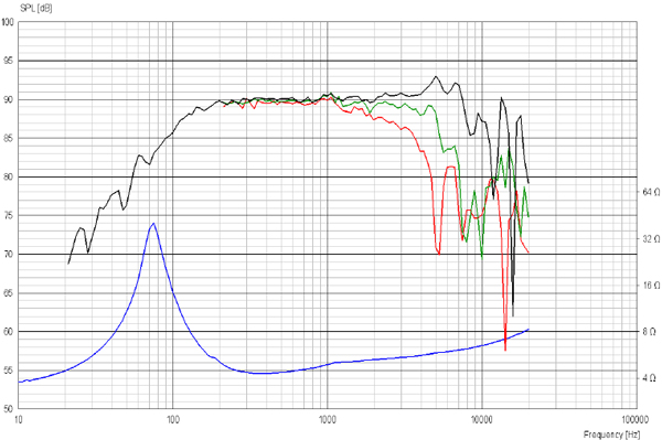
Comment