Troubleshooting Crossover

Collapse
This topic is closed.
X
X
 
  • Time
  • Show
Clear All
new posts
  • craigrhyne
    Junior Member
    • Jul 2009
    • 11

    Troubleshooting Crossover

    Hey Guys,

    I'm not sure if the DIY forum is the appropriate place for this post, but it seemed like a person who knows how to design/build a crossover would be excellent at troubleshooting one This is, after all, still a DIY project.


    About 6 months ago I picked up a used set of KEF 207 series reference speakers. At the time of purchase the speakers were both functioning perfectly. About a week ago, I sat down and flipped the system on, only to find that it sounded very different than usual. Upon further inspection, I determined that two of the six drivers in the left speaker were no longer functioning. At first I expected that the drivers themselves were the culprits, but after bypassing the crossovers I found that the drivers seemed to function normally. I've narrowed down the problem to the crossover network using a voltmeter. The input signal to the PCB is fine, but the output to the speakers is VERY small (barely even shows up on a volt meter and does not produce an audible sound through the driver).

    Here is a pic of the actual speaker:

    Click image for larger version

Name:	IMAG0034.webp
Views:	24
Size:	16.4 KB
ID:	944071

    The drivers in question are the very top silver super HF tweeter, and the top 10" mid-range woofer. The inputs on the back of the speaker are separated into three sets of posts. The lowest set of posts drive the lower two 10" woofers, the middle set of posts drive the upper 10"woofer and the outer gray portion of the 6" driver, and the upper set of posts drive the center silver section of the 6" driver and the small silver stand alone tweeter on the very top. There is also a set of plugs that adjust the tonal balance of the speakers built into the input plate. Here is a picture to help explain what I am talking about:

    Click image for larger version

Name:	IMAG0039.webp
Views:	22
Size:	23.4 KB
ID:	944072

    A pic of the crossover:

    Click image for larger version

Name:	Picture22.webp
Views:	22
Size:	62.5 KB
ID:	944073


    I have no idea what might have caused the damage to the crossover. I do, however, have a roommate (who swears he doesn't know anything about it) so who knows.. Can anyone give me some pointers on how to go about troubleshooting this crossover? The "crossover" appears to actually be three separate crossovers (One for each set of posts). I found it interesting that half of the drivers on the HF board work, and half of the drivers on the mid-range board work. It seems more logical that one entire board would fail. Assuming I can determine the faulty component, I have absolutely no qualms about replacing parts on the pcb.

    Also, I've posted low res cellphone pics in the thread for general purposes. If anyone needs high res pics, just let me know.

    Thanks,
    Craig Rhyne
    Last edited by theSven; 05 July 2023, 09:37 Wednesday. Reason: Update image location
  • BOBinGA
    Senior Member
    • Mar 2009
    • 303

    #2
    WOW! That's a crossover that would even make Jon Marsh jealous.

    But seriously, Start with the simple things first. I don't see any obviously burnt components, but look closely. Check for any fuses hidden in the box perhaps near the driver ends of the wire. Then check the wires themselve and make sure its not simply a cold solder joint to the crossover or a bad connector on the speaker end.

    From your picture, it is pretty obvious that the left section is the lower woofer crossover, so don't look there. The center section is the mid crossover, so find the wires going to the bad upper woofer and find where they go into the crossover. Then trace them back through all the components that are directly between the speaker wire and the input wire to that section of the crossover. One of those components is the likely culprit. I see what looks like a lot of aluminum can electrolytic capacitors. They are the components most likely to fail. Look for any of them that look puffed up. If it is, its bad and needs to be replaced.

    Finally, the tweeter crossover is the right hand section in your picture. Same thing - trace the speaker lead back to the input and check comnponents between them. I don't see any electrolytics there, so look for burnt resistors. The picture is a little fuzzy, but there is a small upright component right below the big capacitor that looks like it might be either an electrolytic or a light bulb. Check that. Light bulbs are often used as protection devices. If its bad, replace it. You can replace it with a regular 1 amp AGC fuse if you want.

    Hopefully this helps.

    -Bob
    -Bob

    The PEDS 2.1 mini system
    My A7 Project - another small desktop speaker
    The B3 Hybrid Dipole - thread incomplete and outdated

    Comment

    • JonP
      Senior Member
      • Apr 2006
      • 692

      #3
      Wow... no kidding about the large part count on that thing!

      If it's easy to lift up the boards to look at the underside, you might look carefully at the solder joints. A classic failure with them is when the part lead that sticks out into the blob of solder attaching it to the pad breaks loose. It looks like the joint has a tiny seam around the wire, rather than the perfect "wetting" of the solder flowing over it. Just remelt it with the iron and its good as new. Thing about those, is that usually they only partially open up, or with a bit of vibration will make contact again, so it's not as likely as your cause. But occasionally they go full open and stay that way.

      You can try pressing/moving parts gently with a finger while playing music, include the wires off the board, and see if something starts working again. Then resolder the offending joint(s).

      Just occurs to me looking at that multi-shorting bar assembly, have you tried the more obvious of making sure the binding posts are all tight, etc?

      It does sound like some component opened up on you, and you'll have to go thru it part by part... If so, start by finding the inputs and start tracing the path with your voltmeter, till you find where it stops. With better pics, we could help with reverse engineering things if you get lost in the maze... 8O

      Oh, almost forgot, you want to be REAL careful with the volume with driving the drivers full range, sensitive tweeters and small midranges are easy to blow without the protection of the crossover.

      Comment

      • Undefinition
        Senior Member
        • Dec 2006
        • 577

        #4
        That crossover is insane. Each filter has more parts than I think any of my crossovers do.

        The only other thing I'd toss in is that resistors can burn up if driven too hard (their job is to turn energy into heat, after all). However, looking at your pic, I don't see anything obvious.

        Does anything on the board smell smoky or like burnt plastic?
        Isn't it about time we started answering rhetorical questions?
        Paul Carmody's DIY Speaker Site

        Comment

        • Jonasz
          Senior Member
          • Nov 2004
          • 852

          #5
          Well, the speakers are very expensive so it's nice to see you get a lot of parts for the money. According to John Atkinson at Stereophile they both sound and measure nicely. :P
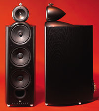
          The very last review I wrote for Hi-Fi News & Record Review (these days just plain Hi-Fi News)—before crossing the Atlantic to take up the reins at Stereophile in May 1986—was of KEF's then-new flagship speaker, the Reference 107. That rave review appeared in the English magazine's July 1986 issue, and was followed by equally positive reports from Stereophile's writers.

          Comment

          • 5th element
            Supreme Being Moderator
            • Sep 2009
            • 1671

            #6
            One thing that could add to the crossover complexity are the "tonal balance" options. For the tweeter/midrange network this is more then likely going to be switching in and out different Lpad values. For the bass network this could be a lot more complex, maybe switching between one crossover and another, maybe a tapped inductor.

            Another thing to remember is that this is a 6 driver system. The two bass drivers, lower midrange, upper midrange and coaxially mounted tweeter, then the super tweeter. Each driver will have it's own crossover, even the twin bass drivers might have different xovers too. The two mids will have bandpass filters and by the looks of the stereophile measurements, steep orders used, so this more then explains why there are loads of crossover components! Heck they might even low pass the coax tweeter >.<

            Resistors can be designed to have something of a 'fuse' effect at high powers and in these cases they leave virtually no sign of damage apart from the fact they are open circuit.

            I can see how the lower midrange driver might have been over driven and the xover die, as this range generally has a lot of energy contained within it, but the super tweeter? 15khz and up? Anything after the main capacitor (which should be the first component in the network) is going to see virtually no power so the chance of blowing one of those is very slim indeed. I do wonder how the thing stopped working in the first place.

            Testing the resistors and inductors is very easy, a continuity tester will let you know if they are broken. If the resistance measures in the 100 of ohms range or reads infinity/open circuit then an inductor/resistor is probably dead.

            Any shunt components though (those that connect to ground) are unlikely to be the cause of the problem, even if they were to all suddenly explode, leaving only the series connected components, the individual drivers would still make a lot of noise, only more so with the shunts out of the picture then with them in it.

            A fuse or lightbulb would make the most sense.
            What you screamin' for, every five minutes there's a bomb or something. I'm leavin' Bzzzzzzz!
            5th Element, otherwise known as Matt.
            Now with website. www.5een.co.uk Still under construction.

            Comment

            • craigrhyne
              Junior Member
              • Jul 2009
              • 11

              #7
              Ok guys, I appreciate all of the responses! I've been through all of the resistors and inductors with a volt meter. Several resistors read very close to zero and as high as 82 ohms, but all seem to be very near to the values printed on the top of the resistor. All of the coils read very close to 0 ohms. (Right now I'm working with a cheapie volt meter.. should be able to retest when I go home and grab a better volt meter this weekend.)

              Here is a much higher res pic of the crossover (actually is seems that photo-bucket automatically re-sizes photos. Is there a way to attach files to a post?):

              Click image for larger version  Name:	DSC_0461.webp Views:	0 Size:	95.0 KB ID:	944074


              I've wiggled all of the components while the speakers were playing to no avail. Any other ideas? Is there a way to test capacitors while still on the board?

              Thanks,
              Craig Rhyne
              Last edited by theSven; 05 July 2023, 09:38 Wednesday. Reason: Update text

              Comment

              • JonP
                Senior Member
                • Apr 2006
                • 692

                #8
                Even if you have a LCR meter, it can be difficult or impossible to measure some parts in circuit, due to them being connected to others, and creating multiple paths, some may be in parallel, etc.

                Know that your meter results with the resistors can be affected by this, though it sounds like you got mostly the right answers.

                I'd say the most likely parts to have problems would be the resisitors, then the electrolytic caps, then maybe the poly caps. Thick wire inductors like those just about can't open up, without truly serious abuse. Fire might have to occur. :B I've seen low grade electrolytics erode their own leads, and open up that way, rare though. Pushing on them can get the connection to come and go.

                Since you've done a good bit of prodding and poking at parts with no effect, Id' say your next approach would be to map out the inputs and outputs on the boards, play some moderate volume music that covers much of the spectrum, and start tracing the signal path thru the board with your AC voltmeter. Careful not to short traces, of course. Sooner or later, you'll find a spot where it stops.... and that's your component/connection/etc.

                Comment

                • Renovator
                  Junior Member
                  • Jan 2010
                  • 21

                  #9
                  Originally posted by JonP
                  Even if you have a LCR meter, it can be difficult or impossible to measure some parts in circuit, due to them being connected to others, and creating multiple paths, some may be in parallel, etc.

                  Know that your meter results with the resistors can be affected by this, though it sounds like you got mostly the right answers.

                  Not an area I know a lot about.
                  Would it there be any benefit in pulling the other cross over out so he can compare readings? He may not be able to get exact readings as per reason above, but would it help to find where the problem is?

                  Best of luck
                  Lewis

                  Comment

                  • fbov
                    Senior Member
                    • Jun 2008
                    • 479

                    #10
                    Actually, having a working circuit always makes troubleshooting easier. Stereo amps with one bad channel, for example.

                    The only trick is that when the signal is different, it may not be clear what component's responsible, but at least you've isolated it to one area of the PWB.

                    Very nice speaker, BTW, certainly worth the time to troubleshoot...

                    Have fun,
                    Frank

                    Comment

                    Working...
                    Searching...Please wait.
                    An unexpected error was returned: 'Your submission could not be processed because you have logged in since the previous page was loaded.

                    Please push the back button and reload the previous window.'
                    An unexpected error was returned: 'Your submission could not be processed because the token has expired.

                    Please push the back button and reload the previous window.'
                    An internal error has occurred and the module cannot be displayed.
                    There are no results that meet this criteria.
                    Search Result for "|||"