MASONIC 10:69 - TL Subwoofer

Collapse
This topic is closed.
X
X
 
  • Time
  • Show
Clear All
new posts
  • rdrowley
    Member
    • Sep 2010
    • 87

    MASONIC 10:69 - TL Subwoofer

    I recently built 4 TriTrix TL's and love them, but, it got me very interested in quarter wave transmission lines. I have an idea rattling around in my head and the very attractively priced Dayton SD270-88 put my idea into action. But, before I make chips fly I thought I would throw my idea out there for some criticism or other input.

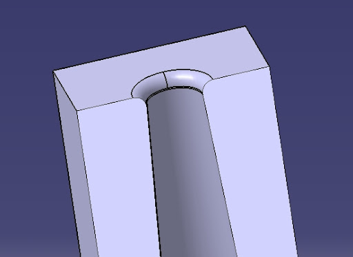
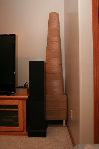
    My idea is to make something that looks like this:


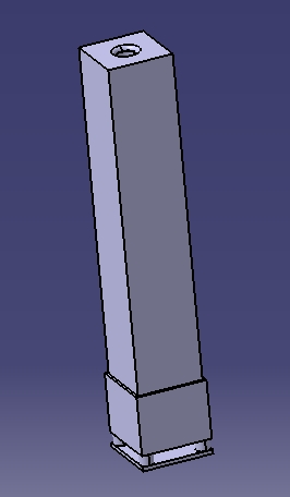
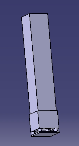
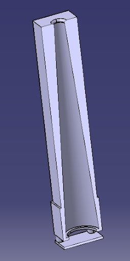
    I'm going to call it the MASONIC 10:69. I'm going to call it this because it will be made out of 564 layers of 1/8th inch thick Masonite, which will make a tapered quarter-wave transmission line 69 inches long. The 10 comes from the fact that I'm using a 10 inch woofer.

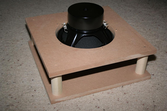
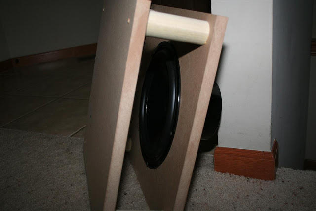
    After a LOT of reading from the material on quarter-wave.com I think I finally figured out what I had to do to make this work. The first thing to do was to pick a driver. PE getting rid of their shielded SD270-88 subwoofers provided that opportunity. From the driver parameters you find the Fs, which is 30Hz in this case. The other parameter mentioned is Qts with a recommended value of .4 ish, this driver has a Qts of .44, so I thought it was close enough. The other benefit of using this driver was it has the same Fs of several of the other higher quality 10" drivers from PE, so if I don't like the driver I can just swap it out. After picking the driver I used the alignment tables from Mr. King, and using a 0.1 SL/S0 I found the length to be 68.9 inches (which I conveniently rounded to 69 inches). I have included this information on the second page of the attached file. The Bottom is 13"x13". I thought that having an 11" diameter hole just inside the baffle would be fine, but I'm not really sure if that is enough breathing room for the woofer (any suggestions?), and that calculated out to a 3.5" diameter opening on the top in order to follow the 0.1 SL/S0 recommendation.

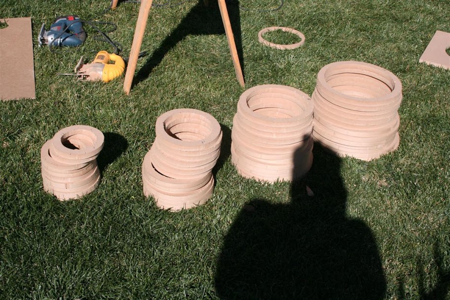
    After that I got busy on the math and came up with a hole diameter for every layer in my 564 layer stackup. The information for that is on page 1 of the attached file. The first 6 and last 6 layers are different than the rest because on the bottom the last 6 layers are for the mounting of the driver.


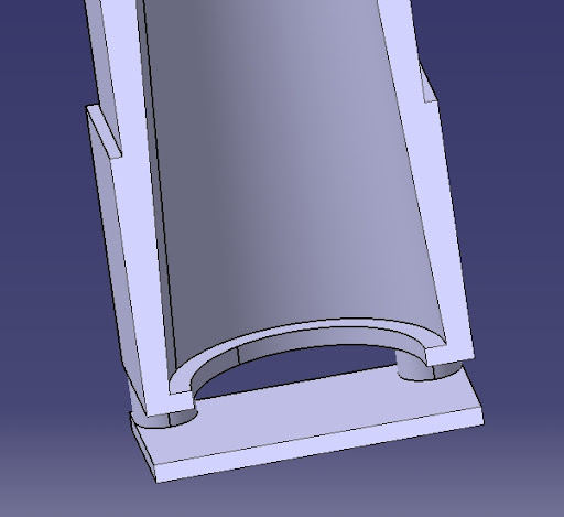
    The top 6 layers are for the end port roundover.


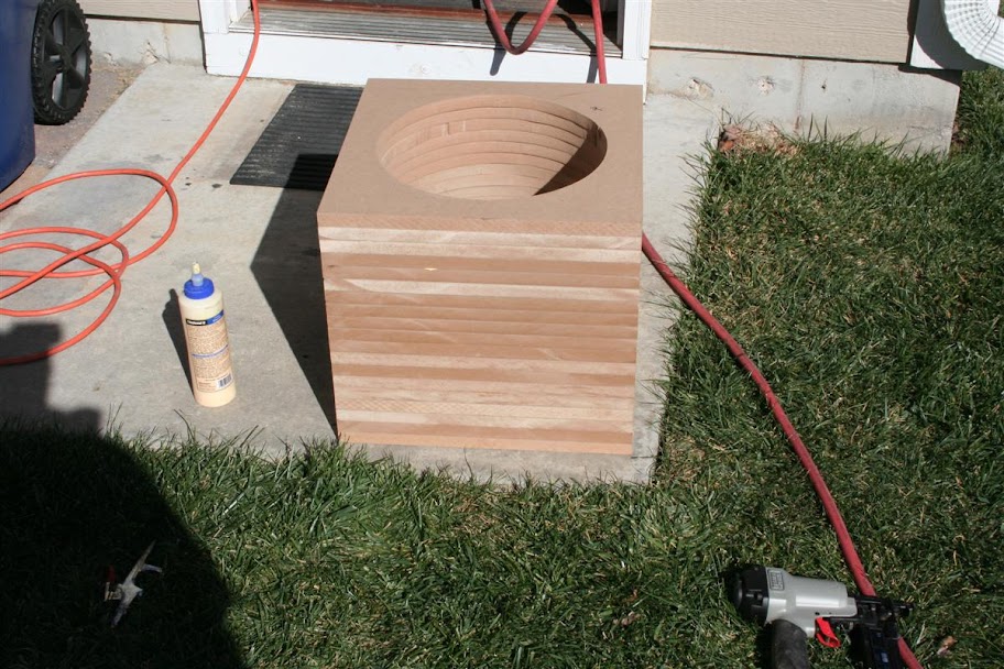
    I want to use the information in the tables to cut the correct diameter hole in every level, then glue the levels together with either contact cement or some other glue concoction. I don't really want to use contact cement because of the wait after application before install (usually about 15 min), and the inability to move the layers once they touch, so...if you have any suggestions here please speak up.

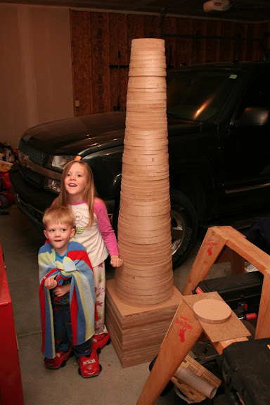
    In the end these will be about 74 inches tall (just over 6 feet). They have a step at 10 inches tall so that I can drop my layer sheet size down to a 12"x12" square instead of a 13"x13" square helping me get more squares out of a sheet of Masonite (32 instead of 21), fortunately for me I have a near limitless supply of VERY cheap Masonite available...I think it'll cost me about $0.80 for ALL the Masonite for this project (approximately 22 sheets).

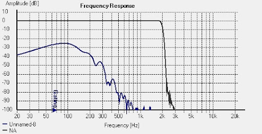
    I'm hoping that by doing a TQWT that tapers in a cone instead of just in 1 dimension that I will get better bass extension on the first system resonate frequency, which should be in the low 20Hz area. But, I have a lot of work ahead of me before that! Good thing I have a hole cutter on my Dremil Tool that works perfectly on Masonite...

    It is going to take me a while before I get this completed (even though the speaker gets here today!), so if you have any input please feel free to make any criticisms or suggestions...especially if you think I'm exceptionally crazy in thinking this will work.
    Attached Files
    -Ryan
  • ruseriousclark
    Member
    • Feb 2007
    • 37

    #2
    WOW! Quite the undertaking.

    Epoxy. Just stagger your gluing such that you are gluing sections together while others dry then assembling larger glued sectoins togerther until complete. Did this with a countour cabinet design built with 1/4" HDF. Using the trim bit on the router after each sections assembly to get a smooth finish.

    Good luck doing this without and CNC machine.
    <-- Beware of Fluffy...He is the destroyer of Worlds!

    Comment

    • rdrowley
      Member
      • Sep 2010
      • 87

      #3
      Originally posted by ruseriousclark
      WOW! Quite the undertaking.

      Epoxy. Just stagger your gluing such that you are gluing sections together while others dry then assembling larger glued sectoins togerther until complete. Did this with a countour cabinet design built with 1/4" HDF. Using the trim bit on the router after each sections assembly to get a smooth finish.
      Could you be more specific? There are a TON of different kids of epoxy out there...
      -Ryan

      Comment

      • Solid7
        Member
        • Jul 2010
        • 96

        #4
        Did you design that in Catia V5 on work time? :twisted: :B

        Comment

        • rdrowley
          Member
          • Sep 2010
          • 87

          #5
          Originally posted by Solid7
          Did you design that in Catia V5 on work time? :twisted: :B
          Lol, nah, I have it at home
          -Ryan

          Comment

          • Txgrizzly
            Senior Member
            • Jun 2009
            • 235

            #6
            may i make a suggestion on making the tapered tube... i would glue up a mold out of some cheap wood and then as you are gluing your layers of Formica you have a mold to keep your tolerances... just make sure you cover your mold with wax paper or something so you can remove it... by the way your mold doesn't have to be round you can make it square just make sure your dimensions are correct.

            Comment

            • numberoneoppa
              Senior Member
              • Sep 2009
              • 535

              #7
              Originally posted by rdrowley
              Could you be more specific? There are a TON of different kids of epoxy out there...
              Your standard 30 minute 2-part epoxy would work fine.
              -Josh

              That feeling when things are finally going right. Yeah, that one.

              Comment

              • Solid7
                Member
                • Jul 2010
                • 96

                #8
                Originally posted by numberoneoppa
                Your standard 30 minute 2-part epoxy would work fine.
                And would be cost prohibitive...

                Take it from me, because I am the king of expensive projects. :B

                Comment

                • Paul K.
                  Senior Member
                  • Jul 2008
                  • 180

                  #9
                  Approximate performance graph

                  I modeled your proposed tapered line using Martin's MathCad based modeling worksheets. I used a stuffing density of 0.75 lb/cu.ft. in the first ~27" of the line (towards the woofer end). I used the specs published by PE for the SD270-88. I've attached two different graphs showing the expected SPL versus frequency for a 1-watt input into this nominally 4-ohm driver. The first graph represents your intended configuration. As you can see the response is pretty lumpy, although as a subwoofer, it might not matter all that much. That first big dip in the response is caused by the woofer being located at the very beginning of the line. You could increase stuffing density and/or length to smooth out the response some, but at the sacrifice of F3. The second graph shows how the response would improve if the woofer were located around 20% (13-14") from the beginning of the line. That first big dip has been mitigated, and the other ripples aren't quite as large. For this one, the same stuffing density is used but with the first half of the line stuffed.
                  Paul
                  Attached Files

                  Comment

                  • ---k---
                    Ultra Senior Member
                    • Nov 2005
                    • 5204

                    #10
                    Paul,
                    Thanks for modeling that. I was wondering what the models would look like. Based on those models, I wouldn't call that design a subwoofer. But it should would add nice chest thumping bass that so many like.
                    - Ryan

                    CJD Ochocinco! ND140/BC25SC06 MTM & TM
                    CJD Khanspires - A Dayton RS28/RS150/RS225 WMTMW
                    CJD Khancenter - A Dayton RS28/RS150/RS180 WTMW Center

                    Comment

                    • Paul K.
                      Senior Member
                      • Jul 2008
                      • 180

                      #11
                      You're welcome. To improve the bass response, make F3 lower IOW, the volume contained within the line needs to be larger, just like for any other type of bass enclosure. The taper and length are pretty close to optimum as is.
                      Paul

                      Originally posted by ---k---
                      Paul,
                      Thanks for modeling that. I was wondering what the models would look like. Based on those models, I wouldn't call that design a subwoofer. But it should would add nice chest thumping bass that so many like.

                      Comment

                      • rdrowley
                        Member
                        • Sep 2010
                        • 87

                        #12
                        Originally posted by Paul K.
                        I modeled your proposed tapered line using Martin's MathCad based modeling worksheets. I used a stuffing density of 0.75 lb/cu.ft. in the first ~27" of the line (towards the woofer end). I used the specs published by PE for the SD270-88. I've attached two different graphs showing the expected SPL versus frequency for a 1-watt input into this nominally 4-ohm driver. The first graph represents your intended configuration. As you can see the response is pretty lumpy, although as a subwoofer, it might not matter all that much. That first big dip in the response is caused by the woofer being located at the very beginning of the line. You could increase stuffing density and/or length to smooth out the response some, but at the sacrifice of F3. The second graph shows how the response would improve if the woofer were located around 20% (13-14") from the beginning of the line. That first big dip has been mitigated, and the other ripples aren't quite as large. For this one, the same stuffing density is used but with the first half of the line stuffed.
                        Paul
                        Yes, thank you for running that! That is nice to see. I wanted to place the driver up the side about 20% or so, but the inside is basically a tube, and I didn't know how to install a driver into the side of a tube. The thing I saw with Martin's models is it was essentially a 2D representation. I'm doing my design the way I am to see if a 3D system behaves any differently than a 2D system does.

                        However, now that you showed me those models I'm thinking of increasing the S0 (and consequently the SL) of the system to increase the internal volume. Do you have a suggestion on a S0?
                        -Ryan

                        Comment

                        • Paul K.
                          Senior Member
                          • Jul 2008
                          • 180

                          #13
                          I'll take a look at this later today and see what I can come up with. I assume you're goal is to make F3 lower by increasing the volume. Do you have an F3 you'd like to obtain? Also, how big can this box be?
                          Paul

                          Originally posted by rdrowley
                          Yes, thank you for running that! That is nice to see. I wanted to place the driver up the side about 20% or so, but the inside is basically a tube, and I didn't know how to install a driver into the side of a tube. The thing I saw with Martin's models is it was essentially a 2D representation. I'm doing my design the way I am to see if a 3D system behaves any differently than a 2D system does.

                          However, now that you showed me those models I'm thinking of increasing the S0 (and consequently the SL) of the system to increase the internal volume. Do you have a suggestion on a S0?

                          Comment

                          • rdrowley
                            Member
                            • Sep 2010
                            • 87

                            #14
                            Originally posted by Paul K.
                            I'll take a look at this later today and see what I can come up with. I assume you're goal is to make F3 lower by increasing the volume. Do you have an F3 you'd like to obtain? Also, how big can this box be?
                            Paul
                            I was hoping to get an F3 at 30 or below, but don't know if this is possible considering the driver. I think I can make it so the inside diameter can be 14 inches. I don't think making it any taller is an option based on Martin's alignment tables. Also, I'm going to cut it off at 80Hz and let my other speakers take care of the rest of the sounds above that, so the oscillations you showed shouldn't be too much of as issue.
                            Last edited by rdrowley; 29 October 2010, 11:02 Friday.
                            -Ryan

                            Comment

                            • Paul K.
                              Senior Member
                              • Jul 2008
                              • 180

                              #15
                              I remodeled it with a starting diameter of 14" and an ending diameter of 4.5", which makes the taper just slightly less than 10:1, with a length of 69" and stuffing density of 0.75 lb/cu.ft. in the first 27-28" of the line, for a total stuffing amount of ~24 ounces (and, of course, with the woofer located at the very beginning of the line). I've attached the new response graph which shows F3 at 31-32 Hz.
                              Paul

                              Originally posted by rdrowley
                              I was hoping to get an F3 at 30 or below, but don't know if this is possible considering the driver. I think I can make it so the inside diameter can be 14 inches. I don't think making it any taller is an option based on Martin's alignment tables. Also, I'm going to cut it off at 80Hz and let my other speakers take care of the rest of the sounds about that, so the oscillations you showed shouldn't be too much of as issue.
                              Attached Files
                              Last edited by Paul K.; 25 October 2010, 10:13 Monday.

                              Comment

                              • rdrowley
                                Member
                                • Sep 2010
                                • 87

                                #16
                                Originally posted by Paul K.
                                I remodeled it with a starting diameter of 14" and and ending diameter of 4.5", which makes the taper just slightly less than 10:1, with a length of 69" and stuffing density of 0.75 lb/cu.ft. in the first 27-28" of the line, for a total stuffing amount of ~24 ounces (and, of course, with the woofer located at the very beginning of the line). I've attached the new response graph which shows F3 at 31-32 Hz.
                                Paul
                                Thanks Paul. That looks pretty decent for this little cheap driver.
                                -Ryan

                                Comment

                                • Paul K.
                                  Senior Member
                                  • Jul 2008
                                  • 180

                                  #17
                                  You're very welcome and please keep us updated on your progress as well as how it sounds when you're all done building.
                                  Paul

                                  Originally posted by rdrowley
                                  Thanks Paul. That looks pretty decent for this little cheap driver.

                                  Comment

                                  • rdrowley
                                    Member
                                    • Sep 2010
                                    • 87

                                    #18
                                    I finally got started on this one. For those of you who like nekkid electronics...


                                    I was going to use masonite for the wood on this one, but after I ran all the numbers I discovered that by breaking up the diameter cuts into 1/8th inch increments I would cut 6 sheets of masonite to the same diameter. 6 sheets glued together equals 3/4 of an inch, so I decided to just use 3/4 thick MDF. Doing it this way will make it a cone shape instead of a rectangle, but will make it lighter and much faster to do, plus it will only take just over 1 sheet of MDF. I also figured out the cost of the glue to adhere the masonite together and it was more expensive than the discounted imperfect (but still perfect for me) sheet of MDF from Lowes. I decided to give it a little more volume per the recommendation here, so the internal lower diameter was increased from 12 to 14 inches. Here is the MDF cut into 16x16 inch squares.


                                    I had what I thought was a great idea to cut the circles. I was going to use my dremil tool with its rotary cutter since it came with a nifty circle cutting guide. Well, the circle guide wasn't long enough to cut a 14 inch circle, so I modified it as shown.


                                    The modification worked quite well cutting .125 inch thick masonite, but when it came to cutting 3/4 MDF instead of being Trial and Error, it was Trial and Failure. That poor dremil was just not made to do that. It took forever and made a nasty cut. Not at all what I was looking for. Now I've got to figure something else out to cut the circles. I've got to use something that makes a narrow cut in order to make the most out of my MDF, so my router is out. I'm currently trying to make a circle guide for my jig saw. Hopefully that will help.

                                    That's hick-up #1 for this project. I still have 273 hick-ups left (274 seems to be my average) so stay tuned.
                                    -Ryan

                                    Comment

                                    • Bent
                                      Super Senior Member
                                      • Sep 2003
                                      • 1570

                                      #19
                                      any chance a large-throat scroll-saw is available ???

                                      Comment

                                      • rdrowley
                                        Member
                                        • Sep 2010
                                        • 87

                                        #20
                                        Originally posted by Bent
                                        any chance a large-throat scroll-saw is available ???
                                        I wouldn't even really need a large throat saw, a normal one would do, but no, I don't have one or have access to one.
                                        -Ryan

                                        Comment

                                        • Txgrizzly
                                          Senior Member
                                          • Jun 2009
                                          • 235

                                          #21
                                          do you have a Jasper circle jig to use with your router? using a 1/4" up-cutting spiral bit is only going to remove 1/4" of material... where are you trying to save material at?

                                          Comment

                                          • rdrowley
                                            Member
                                            • Sep 2010
                                            • 87

                                            #22
                                            Originally posted by Txgrizzly
                                            do you have a Jasper circle jig to use with your router? using a 1/4" up-cutting spiral bit is only going to remove 1/4" of material... where are you trying to save material at?
                                            I don't have a Jasper jig, but a 1/4 router is too large. I'm trying to get 4-5 rings or layers per 16x16 sheet and in order to do that I need to use something that leaves less than 1/8 inch wide cut.
                                            -Ryan

                                            Comment

                                            • Solid7
                                              Member
                                              • Jul 2010
                                              • 96

                                              #23
                                              Originally posted by rdrowley
                                              I don't have a Jasper jig, but a 1/4 router is too large. I'm trying to get 4-5 rings or layers per 16x16 sheet and in order to do that I need to use something that leaves less than 1/8 inch wide cut.
                                              But the question is - will you actually be able to work within this parameter when cutting with a hand tool? (hand, as in non-automated) You will have to be a phenomenal wood worker, and even then, the effort for the time spent will be... trying, at best.

                                              Just saying...

                                              Comment

                                              • rdrowley
                                                Member
                                                • Sep 2010
                                                • 87

                                                #24
                                                Cutting Done!

                                                I made some good progress the last few days. I ended up just cutting the circles with a jig saw. I attached them to a saw horse at the center point then basically had to hold the jig saw still and rotate the wood about the center point. Far from perfect, but not too bad for what I'm trying to accomplish.

                                                Here are the pieces cut out before I glued them.


                                                Here is the square section all glued together.


                                                I actually made it in 5 sections so I could more easily carry it downstairs. Once it is there I will glue the sections together and install the speaker. Since my kids were able to help me with some parts of it I thought I would include them in the picture. They also give you a good idea of how big it is. They like to call it the volcano and are trying to convince me to let them paint it brown with red/yellow/orange flowing out the top...


                                                I've got a bit of sanding on the outside to make it a viable addition to our theater, but I'm going to set it up and see how I like it before I spend a lot of time sanding and painting it. So far it's doesn't have a good SAF rating. We'll see how that ends up.
                                                -Ryan

                                                Comment

                                                • cjd
                                                  Ultra Senior Member
                                                  • Dec 2004
                                                  • 5570

                                                  #25
                                                  You could just make a frame and wrap the whole thing in cloth, so it's square all the way up.

                                                  Looks interesting for sure. You going to try to smooth the inside as you go also? A wide flap-disk might help smooth out the irregularities without too much risk of accidental gouging or otherwise making too dramatic a change.
                                                  diVine Sound - my DIY speaker designs at diVine Audio

                                                  Comment

                                                  • rdrowley
                                                    Member
                                                    • Sep 2010
                                                    • 87

                                                    #26
                                                    Originally posted by cjd
                                                    You could just make a frame and wrap the whole thing in cloth, so it's square all the way up.

                                                    Looks interesting for sure. You going to try to smooth the inside as you go also? A wide flap-disk might help smooth out the irregularities without too much risk of accidental gouging or otherwise making too dramatic a change.
                                                    I'm going to give it a try first then see if I want to make it a permanent addition to the house. If I like it and think it sounds good then I'll sand down the inside as well. I actually have been trying to do so as I went, but it was slow going with a 2 inch PVC pipe wrapped in sandpaper. I'm liking the flap disk idea a lot...
                                                    -Ryan

                                                    Comment

                                                    • Solid7
                                                      Member
                                                      • Jul 2010
                                                      • 96

                                                      #27
                                                      I actually built myself a "lathe" once for a project like this. Basically, I mounted a washing machine motor on a beam consisting of 2 6x6's. At the opposite end, I made an adjustable frame. Can't remember if I used bearings or just roller, but it worked pretty well. I adjusted the non-driven end to "best fit" my workpiece, and used the apparatus to sand the whole piece smooth. It came out very nice.

                                                      I got the inspiration for that idea from an old shipyard worker that I knew. Ah, the stories he told about how to do a job without giant sized machinery...

                                                      Comment

                                                      • rdrowley
                                                        Member
                                                        • Sep 2010
                                                        • 87

                                                        #28
                                                        I was able to get the sub-woofer installed and give it a workout today. Here are the pics of the last part of the build.


                                                        And the final, albeit unfinished product.


                                                        That is a 40 inch tall TriTrix in front of it, just to give you an idea how tall it is.

                                                        Here is the frequency response I measured.


                                                        The blue line is the input from the speaker. I think my measurements are a little off as I don't have a calibrated mic, and the response of the mic I do have shows a drop off of about -3dB under 100Hz. Taking that into account it's very close, but not quite, the F3 of 30 I was hoping for.

                                                        As for listening...it is incredible how much better it sounds than the 8in HTIB subwoofer I had before. Previously, when I listened to the beginning sequence in Bolt or the fighting sequences in IronMan 2 the deep subwoofer sounds were atrocious. With this thing the sounds are tight and very deep. I had to open the doors adjacent to the theater area because they were rattling in their frames. Although at the very low end (~20Hz) it runs out of ability and gives some negative sounding vibes. My wife was very impressed and asked "Is this how these movies are supposed to sound? Are they really supposed to go this low? I can FEEL them!" I politely told her that it was way closer than what we had before, but we weren't quite there yet, and that $40 wouldn't get us there. But, I've got to say, I would have never thought that $40 (for the driver and wood) could have sounded so good.

                                                        I think I need to take it outside again and give it a good sanding to make it look good, maybe add a little paint, then we will probably keep it till I get my Dayton RS 15 incher. In the mean time I'm going to keep listening to it and get it broken in good then measure it again.
                                                        -Ryan

                                                        Comment

                                                        • cbark
                                                          Member
                                                          • Jan 2010
                                                          • 97

                                                          #29
                                                          I say skip the time consuming sanding, and get the wife to agree to a safari theme decor. Put a couple of those long twig branch looking things in the top of your monster and you are done! It will blend right in. :lol:

                                                          Comment

                                                          • 1Michael
                                                            Senior Member
                                                            • Sep 2006
                                                            • 293

                                                            #30
                                                            Skip the paint! Sand them and put poly on them and they will look too cool.
                                                            Michael
                                                            Chesapeake Va.

                                                            Comment

                                                            Working...
                                                            Searching...Please wait.
                                                            An unexpected error was returned: 'Your submission could not be processed because you have logged in since the previous page was loaded.

                                                            Please push the back button and reload the previous window.'
                                                            An unexpected error was returned: 'Your submission could not be processed because the token has expired.

                                                            Please push the back button and reload the previous window.'
                                                            An internal error has occurred and the module cannot be displayed.
                                                            There are no results that meet this criteria.
                                                            Search Result for "|||"