
 Tweet
Tweet
I just finished building a sub (Bill's THT) and bought a Crown XTI 1000. I tried just running an rca -> xlr adapter from my panasonic xr57 to the xti but the level is really low. Assuming I need an cleanbox? Also I saw that there is a mod to flatten the response, some people are saying .47uf and others 1uf caps. Which is the recommended one?
-
-
The 1 uF cap will give you a lower f3. Approximately 16 Hz vs ~34 Hz with the 0.47 uF cap.
using f3 = 1/(2*pi*R*C)
R = 100k - input impedance
C = capacitance in farads -
Sorry to bump this, but the math is wrong.
The factory F3 is 34Hz with the .047uf caps. 1/(2*pi*100000*0.000000047)
.47uf = 3.4Hz
1.0uf = 1.6Hz
Which ever the local place has on hand will do, for future searches.Comment
-
I think you have an extra zero after the decimal point. 0.47 microfarads should be 47 after 6 zeros since the 6th position after the decimal point is millionths.
If that's wrong, someone speak up.
JimComment
-
Soho had an extra zero typed in but his math is otherwise correct. 3.4Hz and 1.6Hz are the correct -3dB values for 100k ohm and .47uF and 1.0uF, respectively, assuming we are talking about a simple passive RC circuit. In other words it really, really doesn't matter. Pick whichever value is cheaper/available/whatever.
Quick and easy web based calculator here:
Comment
-
How are you deciding output seems low, measurements or just listening? IME, a sub doesn't sound terribly loud to the ear when run on its own.Originally posted by dsl1
The Crown specs say the XTi 1000 only needs 1.4v to hit full output into 4 ohms; gain is spec'd at 30.5dB, which is slightly more sensitive than the THX home amp spec of 29dB. It's possible your Panasonic has a *really* weak sub preout, but the receiver sub preouts measured by Sound&Vision are typically capable of 4v-6v and some have been as high 9v. S&V did test an XR70, but it appears all of the lab results are missing from the S&V site...all as in *all*, not just the XR70...bummer. I would double check all settings on the XR57 and XTi and do some measurements with an SPL meter and test tones to get an objective picture of what your THT is really doing.
-BrentComment
-
Stock cap=.047uf; 1/(2*pi*100000*(4.7E-08 ))= 33.86HzOriginally posted by jliedeka
Sub cap=.47uf; 1/(2*pi*100000*(4.7E-07))= 3.39Hz
Sub cap-1uf; 1/(2*pi*100000*(1E-06))= 1.59Hz
The equation was for the stock cap. :TComment
-
-
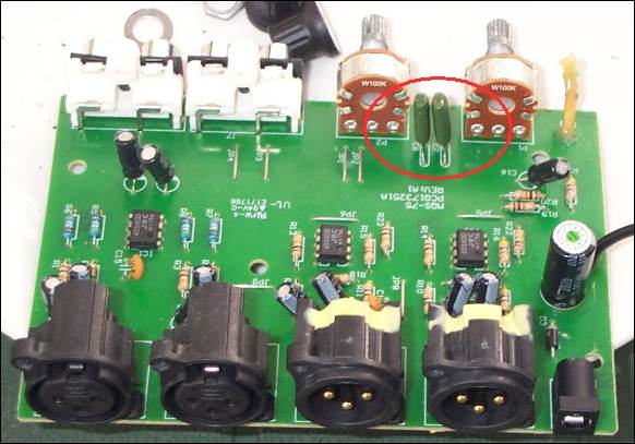
It looks like these are just DC block caps for the output of a a single supply op amp design. It looks like it goes DC power input jack (bottom right) through reverse voltage protection diode (to protect against hooking up an incorrect polarity wall wart) to single bulk electrolytic. The opamps look like they only have a single ceramic bypass cap on them as well (IC1, C15).
In that case, you could probably replace the caps with polarized or non-polarized electrolytics, so long as you put the cathode towards the output with the polarized caps. Check the voltage with a multimeter before you do it though. In any case you could probably find cheap electrolytics locally at a Rat Shack or other place easier than you can find 1uF films. Don't use tantalums though, even though they will 'work if you hook them up with the right polarity the testing I have seen on them indicates they are awful in terms of distortion. And they are far more costly than film or electrolytics.
Although it makes me wonder, why did they use films in that location when they have polar electrolytics in the signal path everywhere else? Hmm.Comment


Comment