Duelund meets Dunlavy (aka Duelund meets transient perfect)

Collapse
This topic is closed.
X
X
 
  • Time
  • Show
Clear All
new posts
  • Dennis H
    Ultra Senior Member
    • Aug 2002
    • 3798

    Duelund meets Dunlavy (aka Duelund meets transient perfect)

    I was sitting around today, wishing I was at RMAF with the gang, and doing my usual multitasking thing -- watching the ballgame on TV and fiddling around on the computer. I was thinking about the old Dunlavy speakers where he uses lots of drivers with 1st order acoustic crossovers to get so-called 'transient perfect' response, meaning they will play a square wave and what the mic picks up looks something like a square wave.

    The problem with 1st order acoustic slopes is almost no drivers can handle that. I got to thinking about the Duelund concept where you stack 2nd order filters at all the XO frequencies and the ultimate roll-off for most of the drivers is steeper than 2nd order. If you did the same thing with 1st order filters, would the sum still retain its 'transient perfect' behavior?

    The answer is YES. Shown below is the theoretical schematic for a 5-way so each driver only has to cover 2 octaves or so. It's just cobbled together with active transfer functions to look at the summed magnitude and phase. Each driver has 4 1st order filters, either highpass or lowpass, all at the same frequencies. Notice that I had to increase the gain of the middle 3 to flatten the response. Once I got the response flat, the phase flattened out and the square wave shaped up.

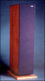
    To build a practical speaker like this, you'd probably need 9 drivers -- W-MW-M-MT-T-MT-M-MW-W. You'd also need a sloped or stepped baffle ala Dunlavy to align the acoustic centers. The big advantage over a Dunlavy would be the steeper acoustic roll-off in the stopband. You might be able to pull it off as a 4-way with the right drivers but I think a 3-way would be pushing it.

    Click image for larger version

Name:	duelund-tp-schem.gif
Views:	5000
Size:	20.6 KB
ID:	870100

    Click image for larger version

Name:	duelund-tp-fr.gif
Views:	3768
Size:	10.5 KB
ID:	870101

    Click image for larger version

Name:	duelund-tp-sqrwv.gif
Views:	3759
Size:	9.8 KB
ID:	870102
    Last edited by theSven; 14 May 2023, 16:50 Sunday. Reason: Update image location
  • brianpowers27
    Senior Member
    • Feb 2009
    • 221

    #2
    Why do you suggest using 9 speakers vs 5 for this design? It seems to me that 2 drivers covering the same range would smear the impulse since you could no longer derive the exact origin of the wave.
    --My Speaker building pages http://sites.google.com/site/brianpowers27speakers/
    --Get yourself on this forum member map! This can help everyone find fellow DIYers in the area.
    --The Speaker DIY resource Database

    Comment

    • Dennis H
      Ultra Senior Member
      • Aug 2002
      • 3798

      #3
      1st order crossovers have weird lobing unless you do the MTM thing. As well, the sound source moves up and down quite a bit as the pitch changes. You could make it work with half the drivers but Dunlavy always seemed to go for a symmetrical layout.

      Comment

      • brianpowers27
        Senior Member
        • Feb 2009
        • 221

        #4
        I am having a hard time imagining how to create this inside of PCD.

        --I assume that all of the filters above are 1st order butterworth filters with a q of .707.
        --Using Arta - Which test can help me to capture a square wave.
        --Could you describe the geometry of the drivers that you simulated above?
        --Does the square wave hold up at different values?

        Note: After reading more of the 1997 Dunlavy posts it seems that the dual drivers were used to control beam width.http://gonecatfishin.net/John%20Dunl...sts%201997.htm
        --My Speaker building pages http://sites.google.com/site/brianpowers27speakers/
        --Get yourself on this forum member map! This can help everyone find fellow DIYers in the area.
        --The Speaker DIY resource Database

        Comment

        • Dennis H
          Ultra Senior Member
          • Aug 2002
          • 3798

          #5
          Originally posted by brianpowers27
          I am having a hard time imagining how to create this inside of PCD.

          --I assume that all of the filters above are 1st order butterworth filters with a q of .707.
          --Using Arta - Which test can help me to capture a square wave.
          --Could you describe the geometry of the drivers that you simulated above?
          --Does the square wave hold up at different values?
          Right on the 1st order Butterworth. Technically, there's no Q for a 1st order filter.

          In ARTA, the latest version lets you record an impulse from an external source -- gunshot, popped balloon, whatever. It also works as a pretty good triggered recording scope. Tell ARTA to start recording, then start a square wave playing from another app, say the demo version of TrueRTA. The advantage of a triggered scope over the scope function in TrueRTA is you capture the first few cycles before room reflections muck up the signal.

          There's no geometry in the sim, just summed electrical signals. Whatever you do for geometry, each driver's acoustic center needs to be the same distance from the ear at the listening position.

          Gotta run, more later.

          Comment

          • augerpro
            Super Senior Member
            • Aug 2006
            • 1867

            #6
            Cool stuff Dennis! I think there is certainly potential in extending this idea to the 1st order and even 3rd order filters too. Kreskovsky went into this more thorougly on his site, but the basic idea is pretty simple, jsut cascade filters all having the same Fc's. Could probably do a cheap proof of concept using all SB drivers.
            ~Brandon 8O
            Please donate to my Waveguides for CNC and 3D Printing Project!!
            Please donate to my Monster Box Construction Methods Project!!
            DriverVault
            Soma Sonus

            Comment

            • Bear
              Super Senior Member
              • Dec 2008
              • 1038

              #7
              Originally posted by augerpro
              Cool stuff Dennis! I think there is certainly potential in extending this idea to the 1st order and even 3rd order filters too. Kreskovsky went into this more thorougly on his site, but the basic idea is pretty simple, jsut cascade filters all having the same Fc's. Could probably do a cheap proof of concept using all SB drivers.
              Domes, domes and more domes.
              Welcome to Rivendell, Mr. Anderson.

              Comment

              • john k...
                Member
                • May 2005
                • 68

                #8
                Hi Dennis,

                Yes, this can be done at infinitum. What you are basically doing is setting up a system transfer function composed of the product of 1st order TFs with different poles.

                Tf(s) = (1 +S1)/(1+S1) x (1 + S2)/(1 + S2) x ..... x (1+Sn)/(1+Sn) where n is the order of the TF. Since each component (1 +sx)/(1+sx) = 1, then TF = 1.0 and you can then factor the numerator to get different band pass, HP and LP filters.

                LP(s) = 1/[(1+S1)x(1+S2)x...x(1+Sn)]

                HP(s) = S1xS2x...Sn/[(1+S1)x(1+S2)x...x(1+Sn)]

                The band pass filters are composed of what is left of the numerator.

                Your construction makes it a little easier to see the result.
                John k....
                Music and Design

                Comment

                • brianpowers27
                  Senior Member
                  • Feb 2009
                  • 221

                  #9
                  Originally posted by john k...
                  Hi Dennis,

                  Yes, this can be done at infinitum. What you are basically doing is setting up a system transfer function composed of the product of 1st order TFs with different poles.

                  Tf(s) = (1 +S1)/(1+S1) x (1 + S2)/(1 + S2) x ..... x (1+Sn)/(1+Sn) where n is the order of the TF. Since each component (1 +sx)/(1+sx) = 1, then TF = 1.0 and you can then factor the numerator to get different band pass, HP and LP filters.

                  LP(s) = 1/[(1+S1)x(1+S2)x...x(1+Sn)]

                  HP(s) = S1xS2x...Sn/[(1+S1)x(1+S2)x...x(1+Sn)]

                  The band pass filters are composed of what is left of the numerator.

                  Your construction makes it a little easier to see the result.
                  First admission = I am not a math guy and am having a hard time following the formula.

                  It seems as though you are iterating/incrementing through the various drivers in the system with the terms S(n) where n = the order of the driver in the system. I read that you stated that n should equal the order of the transfer function but I assumed that the transfer function would be 1, since they are all 1st order filters.

                  Please help.
                  --My Speaker building pages http://sites.google.com/site/brianpowers27speakers/
                  --Get yourself on this forum member map! This can help everyone find fellow DIYers in the area.
                  --The Speaker DIY resource Database

                  Comment

                  • Bear
                    Super Senior Member
                    • Dec 2008
                    • 1038

                    #10
                    Originally posted by brianpowers27
                    First admission = I am not a math guy and am having a hard time following the formula.

                    It seems as though you are iterating/incrementing through the various drivers in the system with the terms S(n) where n = the order of the driver in the system. I read that you stated that n should equal the order of the transfer function but I assumed that the transfer function would be 1, since they are all 1st order filters.

                    Please help.
                    The idea is cascading poles. Whether this still really fills the concept of a "true" first-order filter is where I think you're getting caught. Simplistically, if you had drivers spaced two octaves apart, the first two octaves would roll off as a first order, then the slope would increase to a second order as the next pole kicked-in, etc. This would help to limit (somewhat) how low tweeters have to go and how high woofers the need to go, but you will still be placing a fairly decent acoustic load on each.

                    For example, the "supertweeter" will be down <20dB just above 1kHz, assuming my math is right and depending upon Fc, when the second pole kicks in (simplistically: Fc(1) ~ 5kHz, Fc(2) ~1250 Hz; each Fc is -3dB, 6dB/octave, 2 octave spacing for each pole). In other words, you are looking for something that can handle LR2 at ~1.5K for a tweeter, which is a pretty special ($$) driver.

                    Oh, yeah, the cabinet will be huge.
                    Welcome to Rivendell, Mr. Anderson.

                    Comment

                    • john k...
                      Member
                      • May 2005
                      • 68

                      #11
                      Originally posted by brianpowers27
                      First admission = I am not a math guy and am having a hard time following the formula.

                      It seems as though you are iterating/incrementing through the various drivers in the system with the terms S(n) where n = the order of the driver in the system. I read that you stated that n should equal the order of the transfer function but I assumed that the transfer function would be 1, since they are all 1st order filters.

                      Please help.
                      Actually, n is the order of the TF. In the system TF there are n poles which can be at n different frequencies (though not required). When you multiply out the TF you will have an nth order polynomial.
                      John k....
                      Music and Design

                      Comment

                      • Bear
                        Super Senior Member
                        • Dec 2008
                        • 1038

                        #12
                        Originally posted by john k...
                        Actually, n is the order of the TF. In the system TF there are n poles which can be at n different frequencies (though not required). When you multiply out the TF you will have an nth order polynomial.
                        John - If you don't use different Fc for each pole, wouldn't this no longer be a first-order filter?
                        Welcome to Rivendell, Mr. Anderson.

                        Comment

                        • john k...
                          Member
                          • May 2005
                          • 68

                          #13
                          Originally posted by Bear
                          John - If you don't use different Fc for each pole, wouldn't this no longer be a first-order filter?

                          Hi Bear,

                          Let's see if I can make things a little clearer. The system TF is composed of the product of n 1st order transfer functions. Thus, the system TF will be of order n as will each of the individual filters for the drivers. The poles of the transfer functions can be unique or all the same. The system will require at most n+1 drivers.

                          The classic case is when n = 2 and the poles at the same. The system TF is

                          (1+s) x(1+s)/ [(1+s) x(1+s)] = (1 + 2s + s^2)/ (1 + 2s + s^2).

                          The TF's for woofer, mid and tweeter are:

                          W = 1/(1 + 2s + s^2).

                          Mid = 2s / (1 + 2s + s^2).

                          T = s^2 / (1 + 2s + s^2).

                          Some of you may recognize this as one alignment of th B&O filler driver crossover where the woofer and tweeter have LR2 responses and the mid is a 2nd order bandpass response (i.e. it rolls off 1st order above and below the center frequency).

                          Now, the actual choice of where the poles are will effect the required gain of the pass band filters, etc.

                          Also note that the system can always have just two drivers. For example, when n = 2 the woofer could be

                          W = (1 + 2s)/ (1 + 2s + s^2)

                          and the tweeter

                          T = s^2 / (1 + 2s + s^2).

                          The acoustic response of the woofer in this case would be identical to the summed response of the woofer + mid in the case where 3 drivers were used.

                          The key here is that we are always starting out with a system TF that = 1.0 since the numerator = the denominator.


                          The problem with these type of crossover is that they can have very uneven polar response with off axis peaks as high as 6dB and on axis there is a requirement that on axis the out put of various driver must cancel to obtain flat response. That is, the inter driver phase differences exceeds 120 degrees.
                          John k....
                          Music and Design

                          Comment

                          • brianpowers27
                            Senior Member
                            • Feb 2009
                            • 221

                            #14
                            Thank you both for the explanation. I understand what is happening much more clearly now.

                            I am starting to feel as if anything approaching transient perfect will almost have to have poor off axis response.
                            --My Speaker building pages http://sites.google.com/site/brianpowers27speakers/
                            --Get yourself on this forum member map! This can help everyone find fellow DIYers in the area.
                            --The Speaker DIY resource Database

                            Comment

                            • Dennis H
                              Ultra Senior Member
                              • Aug 2002
                              • 3798

                              #15
                              Originally posted by Bear
                              In other words, you are looking for something that can handle LR2 at ~1.5K for a tweeter, which is a pretty special ($$) driver.

                              Oh, yeah, the cabinet will be huge.
                              Hi Bear,

                              Yup, there won't be any tiny girly man cabinets.

                              The tweeter load isn't that bad. It's down 15dB at 1250 vs 6dB for an LR2. I'd think any of the currently popular small-faceplate domes could handle it.

                              Click image for larger version

Name:	duelund-tp-tweeter.gif
Views:	3378
Size:	11.7 KB
ID:	853773
                              Last edited by theSven; 14 May 2023, 16:50 Sunday. Reason: Update image location

                              Comment

                              • brianpowers27
                                Senior Member
                                • Feb 2009
                                • 221

                                #16
                                I could almost see this design happening with the following three drivers
                                • Dayton RS28 Maybe the Dayton ND28
                                • Dayton Nd90 3"
                                • Seas P21 8" woofer
                                --My Speaker building pages http://sites.google.com/site/brianpowers27speakers/
                                --Get yourself on this forum member map! This can help everyone find fellow DIYers in the area.
                                --The Speaker DIY resource Database

                                Comment

                                • Dennis H
                                  Ultra Senior Member
                                  • Aug 2002
                                  • 3798

                                  #17
                                  Here are acoustic target curves for the rest of the drivers.

                                  Click image for larger version

Name:	duelund-tp-midtweeter.gif
Views:	3414
Size:	11.2 KB
ID:	853774

                                  Click image for larger version

Name:	duelund-tp-midrange.gif
Views:	3361
Size:	11.2 KB
ID:	853775

                                  Click image for larger version

Name:	duelund-tp-midwoofer.gif
Views:	3256
Size:	11.2 KB
ID:	853776

                                  Click image for larger version

Name:	duelund-tp-woofer.gif
Views:	3344
Size:	11.1 KB
ID:	853777

                                  One important point, these curves are oversimplified. They ignore the low-end roll-off of the woofer and the high-end roll-off of the tweeter. Those two roll-offs should be added to each of the curves to keep the phase and group delay working the way it should. If your woofer rolled off 2nd order at 20Hz and your tweeter rolled off 2nd order at 25K, this is the best square wave you could hope for if you did everything right.


                                  Click image for larger version

Name:	duelund-tp-sqrwv-hplp.gif
Views:	3829
Size:	10.6 KB
ID:	853778
                                  Last edited by theSven; 14 May 2023, 16:51 Sunday. Reason: Update image location

                                  Comment

                                  • Dennis H
                                    Ultra Senior Member
                                    • Aug 2002
                                    • 3798

                                    #18
                                    Originally posted by brianpowers27
                                    I could almost see this design happening with the following three drivers
                                    • Dayton RS28 Maybe the Dayton ND28
                                    • Dayton Nd90 3"
                                    • Seas P21 8" woofer
                                    Keep in mind that, as you decrease the number of drivers, you get hit with a double whammy. You move the crossover frequencies farther apart and the slope in the stopband gets shallower. Your 3" mid will have to be able to pull off 1st order acoustic slopes.

                                    Comment

                                    • Face
                                      Senior Member
                                      • Mar 2007
                                      • 995

                                      #19
                                      It may be possible with Accuton drivers.
                                      SEOS 12/AE TD10M Front Stage in Progress

                                      Comment

                                      • Bear
                                        Super Senior Member
                                        • Dec 2008
                                        • 1038

                                        #20
                                        Originally posted by Dennis H
                                        The tweeter load isn't that bad. It's down 15dB at 1250 vs 6dB for an LR2. I'd think any of the currently popular small-faceplate domes could handle it.
                                        That's about what I had calculated in my head, with the slope getting steeper as the additional first-order poles get stacked on it. I think that some of the small-faceplate SS Illuminators could handle this, but I'll leave it to others to press into lower price points. I'm still learning drivers.

                                        For the mid-tweeter, something like a Neo8 PDR would fit the frequency range, but probably not the dispersion and CTC issues required. The Morel MDM55 would probably make aligning the acoustic centers easier vs. a dome tweeter, but the big Tang Band dome may be the better overall driver. Is there a cone driver that would fit this role?

                                        The mid and mid-woofer look to be the easiest curves to hit. Pick a decent 5" - 6.5" woofer for the MW, put it in enough air, and it should work. Getting the AC aligned will be the trick. Similar story for the mid, though keeping costs "reasonable" may be a challenge. This is also the role where I would expect that you might be able to cut it down to a 4-way.

                                        The real killer in all of this is going to be the enclosure size for the woofers. something like twin 8" or twin 10" drivers would be required, and you are looking at a monster enclosure to get that reasonably flat down to 20 Hz (100+ liters?). A way to cut that down would be to use a compound (isobarik) enclosure, which may also help move the AC to the baffle plane. Fugly, but utilitarian in certain respects.

                                        Just thinking out loud. Pass the popcorn?
                                        Welcome to Rivendell, Mr. Anderson.

                                        Comment

                                        • john k...
                                          Member
                                          • May 2005
                                          • 68

                                          #21
                                          One thing to remember is that all these types of crossovers ultimately can be considered subsets of Small's CV crossovers. The system TF = 1 so if you start with a system TF = (1 + As + Bs^2 + ....+ s^n) / (1 + as + bs^2 + ....+ Ns^n) and let the HP section be

                                          HP = N S^n / (1 + as + bs^2 + ....+ s^n)

                                          Then the sum of the output of the remaining drivers is 1-HP. When you start breaking down the sum part into multiple drivers the problems with spacing and summing off axis are compounded.
                                          John k....
                                          Music and Design

                                          Comment

                                          • Dennis H
                                            Ultra Senior Member
                                            • Aug 2002
                                            • 3798

                                            #22
                                            The real killer in all of this is going to be the enclosure size for the woofers.
                                            Yup, I had a hard time finding good pics of the Dunlavy SCVI ($25K in the 1990s). It's a 4-way with 15", 8", 5.5" and 1". You can just barely make out the stepped baffle with the thick felt surrounding the drivers.

                                            Click image for larger version

Name:	product_119427.jpg
Views:	45
Size:	11.4 KB
ID:	936471

                                            Edit: found the dimensions at Stereophile. I found JA's comments and measurements interesting as well.

                                            Dimensions: 78" H by 18" W by 33" D. Weight: 530 lbs each.

                                            In this age of $70,000-plus "flagship" designs, perhaps $25k is no longer an obscene amount to pay for a pair of loudspeakers. Still, it's mucho dinero. What makes a speaker worth this kind of bread? Does the product's intrinsic value really warrant such a lofty cost, or is it merely a matter of pricing at what the market will bear? The answers to these questions requires careful examination of not only the speaker, but also of the buyer's own soul, priorities, and pocketbook.
                                            Last edited by theSven; 14 May 2023, 16:53 Sunday. Reason: Update image location

                                            Comment

                                            • Dennis H
                                              Ultra Senior Member
                                              • Aug 2002
                                              • 3798

                                              #23
                                              Thanks for pitching in, John. You're a lot better at S-plane math than I am so I appreciate you filling in the technical underpinnings of my somewhat intuitive grasp of these concepts. :T

                                              Comment

                                              • Scottg
                                                Senior Member
                                                • Nov 2006
                                                • 335

                                                #24
                                                Hi Dennis.

                                                Do other filters, say perhaps impedance compensation or BSC, negatively effect the filter's transient perfect performance?

                                                Can this be done with a series crossover?

                                                -Thanks!

                                                Comment

                                                • Dennis H
                                                  Ultra Senior Member
                                                  • Aug 2002
                                                  • 3798

                                                  #25
                                                  Hi Scott,

                                                  The 'filters' shown are the acoustic response including the drivers' natural response. Whatever you do with crossover components is fine as long as the final response of each driver matches the target.

                                                  The idea of a series 4-way or 5-way makes my head hurt. I'm not saying it couldn't be done but I wouldn't know where to begin.

                                                  Comment

                                                  • Winter
                                                    Member
                                                    • Nov 2007
                                                    • 81

                                                    #26
                                                    Note some of the manufacturer's spec for the Dunlavy Signature VI from the link above:

                                                    Acoustic phase response: less than +1 degrees, -2 degrees, 100Hz-10kHz.

                                                    Harmonic distortion: less than 0.3% for an spl of 90dB at 1m for all frequencies above 40Hz.

                                                    Comment

                                                    • Space
                                                      Senior Member
                                                      • Aug 2009
                                                      • 118

                                                      #27
                                                      Click image for larger version

Name:	5WAY_001.JPG
Views:	2844
Size:	33.5 KB
ID:	855108

                                                      Okay, this thread is due for a revival after being referenced by Dennis H on another forum. Also today Zaph posted his test results for the SS 10F midrange, and suggested that its unusually flat response opens the door for a unique application.

                                                      Here's a suggested lineup for Dennis' 5-way crossover:
                                                      >5 kHz : Vifa NE19VTA
                                                      1.25 kHz - 5 kHz : SS 10F-8
                                                      320 Hz - 1.25 kHz: SB15-8
                                                      80 Hz - 320 Hz: SEAS L26
                                                      <80 Hz: Peerless XXLS 835017

                                                      Based on my predilection for OB, the top 4-way is dipole while the 12" is in a box. To avoid seismic hazard there is only a single woofer at the bottom.
                                                      As luck would have it I have all these drivers on hand other than the L26--but do have some RS270s...
                                                      Last edited by theSven; 14 May 2023, 16:52 Sunday. Reason: Update image location

                                                      Comment

                                                      • Dennis H
                                                        Ultra Senior Member
                                                        • Aug 2002
                                                        • 3798

                                                        #28
                                                        Looks interesting, Space!

                                                        Comment

                                                        • David G
                                                          Senior Member
                                                          • Jan 2005
                                                          • 170

                                                          #29
                                                          Space, won't you need a stepped baffle?

                                                          Comment

                                                          • Space
                                                            Senior Member
                                                            • Aug 2009
                                                            • 118

                                                            #30
                                                            In keeping with the theory, yes. I'm not really building this, it was just an inspiration that these drivers could work for the Dennis H 5-way Transient Perfect Mega-Tower.

                                                            In reality this crossover would take extensive experimentation to pull off, and the cabinet is pretty imposing. If it could be done with a DCX2496 I'd consider making a mock-up, but I don't see how that would work. It would probably take several in a daisy chain.

                                                            More the point, this concept appears to incorporate the big idea behind Dunlavy speakers while also improving on their major fault, which was running drivers too far outside their comfort range. That results in excess distortion and coloration. At least that's my understanding.

                                                            Comment

                                                            Working...
                                                            Searching...Please wait.
                                                            An unexpected error was returned: 'Your submission could not be processed because you have logged in since the previous page was loaded.

                                                            Please push the back button and reload the previous window.'
                                                            An unexpected error was returned: 'Your submission could not be processed because the token has expired.

                                                            Please push the back button and reload the previous window.'
                                                            An internal error has occurred and the module cannot be displayed.
                                                            There are no results that meet this criteria.
                                                            Search Result for "|||"