27tbfc/g / 18s/8531g00 / Rss315hf

Collapse
This topic is closed.
X
X
 
  • Time
  • Show
Clear All
new posts
  • SQdude
    Member
    • May 2007
    • 41

    27tbfc/g / 18s/8531g00 / Rss315hf

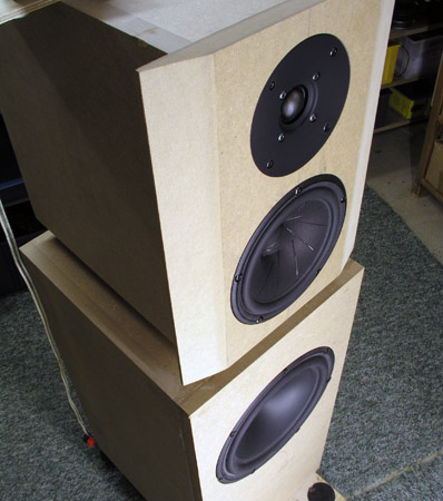
    I've had these drivers for over a year sitting in my closet. I've been hoping to put something together but I guess after taking a year to finish the NatalieP, I kind of got sick of speaker projects (took me so long because of the cabinet work, wanted to go gloss black but never could get the surface perfect. Bondo was a mess and corners weren't perfectly sharp on the top and bottom edges. Never was able to figure out a way to fix them either. I pretty much lost interest. Anyway I digress... back to topic). So with this much money invested in drivers, it'd be a shame not to do anything with them. Then again, I still have to invest in a mic and a sound card. (cheap and effective solutions/recommendations are welcome )

    So first, what do you think of this combination of drivers; the bottom end / midbass region is what I'm worried about the most? In the case of the NatP I think they sound a bit thin (probably due my shallow / heavy stuffed cabinet, with top firing port) in that regard and matting them to a big old servo Velodyne 15" has proven to be difficult. Will the single RSS315 per side give a full and nicely integrated/transitioning midbass and low end?

    Should I just go the simple cabinet route and build a rectangle? A part of me wants something that looks exotic, like Usher's Be-20 but I think my enthusiasm would drop to zero after realizing how much work it would be. I thought about the prefabbed stuff from Madisound, but I already invested in the table saw, clamps, etc; plus they are expensive and shipping would probably be a deal breaker. I then thought about a dipole but I have limited space so acoustically that might not be a good idea.

    Yeah I'm full of words and ideas in this post, hopefully you guys can help steer this project in the right direction. I certainly will need advice/help when measuring and designing the crossover.
  • b_force
    Member
    • Jun 2008
    • 98

    #2
    That's funny I was almost looking at the same driver combination.

    Except for the Scanspeak.

    I found out that a semi passive/active system would work great !
    I'am not sure about your post if you have two RS315, but otherwise, buy one, so you have two !

    Cross the Dayton about 180-200Hz LR4 and maybe boost a little bit (example with LW tranfsorm), but that's a matter of taste.
    Second use the Scanspeak as a mid also hipass crossed LR4 and passive crossed around 2kHz with the Seas tweeter.

    I think you have a very well sounding speaker that is low on THD but has also the dynamics.

    The only negative thing, is that you have to use a second amplifier and a preamplifier to cross and/or boost.
    I don't know your budget, but I think it's worth to look at this option

    Comment

    • Dave Bullet
      Senior Member
      • Jul 2007
      • 474

      #3
      These are 3 nice drivers. I'd be inclined to go with the 15 instead of 18 scanspeak, as you might be able to pull off an LR2 mid/tweeter crossover and have a smoother in room power response.

      The sensitivity of the RSS315 is a little low (86) for the nominal sensitivity of the scanspeak 15. You can always boost the bottom end if you go active with the woofer/mid crossover to allow for baffle step, since the RSS has more than enough xmax to handle some equalization.

      I'd be inclined to go sealed for the RSS, and same again for the 15.

      Model some enclosure designs and post your results back here. Also download BDS from the FRD consortium to add in your intended baffle signature & subtract the one from the measurements you are using to get a feel for crossover possibilities. An RSS per side should give satisfying extension.

      Cheers,
      David.

      Comment

      • SQdude
        Member
        • May 2007
        • 41

        #4
        Thanks. Actually I did have a queestion regarding BDS, what is the correct process on using it? I'd assume using free air (or if not available then perfect) curves, apply that to the given design to see how it alters the response? I guess I'm not understanding your statement "& subtract the one from the measurements you are using to get a feel for crossover possibilities"

        This will be an all passive design, no active solution for the woofer

        Comment

        • Dave Bullet
          Senior Member
          • Jul 2007
          • 474

          #5
          As you probably know, the wavefront goes in all directions (360 degrees or 4 pi radiation) when the wavelength is longer than the narrowest baffle dimension - usually the width in a typical rectangular baffle. As the frequency increases (and wavelength becomes shorter) it starts to reflect more and more from the front of the baffle, until it fully "loads" off the front (180 degree or 2pi propogation) when the wavelength becomes shorter than the baffle with. This transition is called the baffle step. The increase in effective sound pressure (excluding room backwall reflections) is 6dB over the baffle step frequency range.

          When you design a crossover, you build in a certain amount of midrange reduction to account for bafflestep, otherwise the bass will be weak and the speaker sound to thin.

          Due to speakers usually being placed close to a rear wall in most listening situations, 6dB baffle step is often too much compensation. Most designers shoot for about 3 - 5dB compensation. Less when the speakers are used for nearfield listening or when the speakers are truly close to the rear wall.

          Assuming you pick up some existing frequency charts / measurements - you can use them to model a crossover, but first you need to find out the conditions in which those measurements were taken. The conditions are the baffle on which the driver was measured. Unless you design your speaker to use the same baffle dimensions as those measured, your crossover will be wrong, and you will either have too much (or too little) baffle step compensation (BSC).

          Most manufacturers will state the baffle dimensions on which the drivers are measured. Often they will use the IEC standard. If the manufacturer doesn't state what was used - you can guess by any frequency rise in the baffle step region (usually 100 - 600Hz). If the frequency rises by about +6dB, then the driver was measured on a small baffle (baffle step). If the driver has a reasonably flat frequency response all the way down, then the driver is measured on a much larger baffle. This ofcourse assumes the driver has a pretty flat frequency response anyway.

          What you do with the BDS tool from FRC consortium, is to define the baffle dimensions and generate the baffle signature (1). This will create the baffle step rise and baffle ripple depending on driver proximity to the baffle edges.

          Repeat the above, designing your baffle and driver placement. This becomes the target signature to add back into the frequency response curve (2)

          Open up the FRD consortium frequency response combiner (FRC) tool. Load the FRD and load both BDS curves (1) and (2) above. FRC will combine them - subtracting the manufacturers source baffle signature and adding in yours. The result is an FR curve approximating the driver when installed on your target baffle. From there you can hilbert-bode transform to extract minimum phase and commence crossover modeling.

          The above can be used to get you in the ballpark, but real measurements (especially with a 3 way ) are the best way to go.

          David.

          Comment

          • SQdude
            Member
            • May 2007
            • 41

            #6
            Great explanation Dave, thank you. Now to get driver measurements... Maybe Zaph has some.

            Comment

            • Dave Bullet
              Senior Member
              • Jul 2007
              • 474

              #7
              Originally posted by SQdude
              Great explanation Dave, thank you. Now to get driver measurements... Maybe Zaph has some.
              Zaph has the 27tbfc/g. HE doesn't have anything (published at least) for drivers greater than 7". He might have the 18 and possibly the 15.

              Otherwise, use manufacturers measurements (SPLTrace to create the FRD) and apply BDS differences as I've described.

              Actually - Roman Bednarek describes the process way better than my explanation on their websites. Roman's is www.rjbaudio.com.

              Cheers,
              David.
              Last edited by ThomasW; 05 October 2008, 23:40 Sunday.

              Comment

              • SQdude
                Member
                • May 2007
                • 41

                #8
                Anyone have .frd & .zma files for my drivers? Also, if I spl trace the ones zaph has on his site, do I have to subtract the baffle response out, he says the reponses taken on a infinite baffle. I think he used 1/3 octave smoothing too, not sure if that is ok to use then for a trace.

                Comment

                • Dave Bullet
                  Senior Member
                  • Jul 2007
                  • 474

                  #9
                  I only have the 27tbfc/g measurements. I'll post them here with the baffle dimension I used to take the measurement. You are correct around subtracting the BDS signature.

                  What you do is use the BDS tool to model my baffle and driver placement on the baffle and generate the FRD "signature" of the baffle. This new baffle signature you've just generated gets loaded into FRC as the "source" baffle (the one to subtract) along with my original 27tbfc/g measurement. You then click combine and what you end up with is a 27TBFC/G measurement without any baffle signature.

                  Of course you could int he same step model your "target" baffle for your speaker and load the BDS generated FRD for your target into FRC. When you combine you'd get
                  My source 27tbfcg FRD minus my baffle plus your baffle = target curve of the 27tbfcg on your intended baffle.

                  From here you use the same FRC tool to extract minimum phase (this is a Hilbert-Bode transform) then save the new FRD. You can then import this into your xo design tool of choice (PCD, SpeakerWorkshop etc...) and model a crossover. There is one more thing you need to define (setting acoustic offset in the XO modelling tool) but we'll cover that once you have a basic set of FRD files.

                  I cannot help with driver measurements of the other drivers, but see what you can scrounge off the net. If you know the source baffle dimensions on which the FRD was taken - you can follow the above process.

                  I try and avoid smoothed data, but it is good enough to get you in the ballpark. It depends on how perfectionist you are. If you really are trying to eliminate all the 0.5dB peaks and troughs, you need unsmoothed data. However, any speaker +/-2dB over the majority of the spectrum is good enough in most peoples books.

                  Cheers,
                  Dave.

                  Comment

                  • Dave Bullet
                    Senior Member
                    • Jul 2007
                    • 474

                    #10
                    Here's my source TBFCG measurement. the measurement baffle I used (with driver countersunk - ie. flush with the surface of the baffle) was 850mm x 480mm with driver (centre) offset 135mm from the 480mm dimension and 215mm offset from the 850mm dimension.

                    The .txt is a .frd file so rename after downloading.

                    I've also posted a comparison picture between different 27tbfc/g measurements. NB: All were on different baffles. The black is my measurement with .txt uploaded.

                    Cheers,
                    David
                    Attached Files

                    Comment

                    • SQdude
                      Member
                      • May 2007
                      • 41

                      #11
                      Hi All,

                      I am getting some terrible response artifacts with my baffle design (43"x14"). No Matter what I tried I can't seem to position the drivers in BDS to give me a +-1 db window. Any suggestions? Attached is the simulated response (the profile is attached as well, extension needs to change from .doc to .dlp)
                      Attached Files

                      Comment

                      • Dave Bullet
                        Senior Member
                        • Jul 2007
                        • 474

                        #12
                        I thnk what you've got from a tweeter perspective is quite good. Above 2Khz the ripple is smooth. You placed the tweeter at odd distances from each edge (no multiples) which helps smooth the response.

                        Remember - a perfectly flat BDS signature is not the goal, but a flat overall frequency response might be. What I mean is that each driver will have peaks and dips of its own (baffle indepdent) and that combined with the dips and peaks in a baffle signature results in a smoother response.

                        Power response also affects things. Designing for perfect on-axis doesn't mean off-axis response will be any good and vice versa.

                        Remember - you'll be crossing at around 1700Hz or higher with the 27tbfc/g, so anything below this can be eased with crossover design. The hump for all 3 drivers is quite normal. It's how you work this hump in with the natural response of your drivers and crossover slopes and points that blends into a more or less ideal (whatever you target it) amplitude response curve.

                        The only other thing you could do is explore cutting facets or implement a sloped side. These both increase cabinet complexity, so it might end up shifting the problem to construction.

                        Cheers,
                        David.

                        Comment

                        • SQdude
                          Member
                          • May 2007
                          • 41

                          #13
                          Ok. If you think it looks good, its good for me too

                          I plan on felt treatments too. I guess what was throwing me was the big hump that RJB didnt have (http://www.rjbaudio.com/Audiofiles/t...ffraction.html)

                          Comment

                          • ---k---
                            Ultra Senior Member
                            • Nov 2005
                            • 5204

                            #14
                            It looks like you're just using a 1/2" roundover. Going bigger should make the minor improvements you're looking for. When I played with BSD, it seemed like 3/4" roundover was when the roundover started to pay good dividends. My Khanspires use a 1" roundover.
                            - Ryan

                            CJD Ochocinco! ND140/BC25SC06 MTM & TM
                            CJD Khanspires - A Dayton RS28/RS150/RS225 WMTMW
                            CJD Khancenter - A Dayton RS28/RS150/RS180 WTMW Center

                            Comment

                            • SQdude
                              Member
                              • May 2007
                              • 41

                              #15
                              Originally posted by ---k---
                              It looks like you're just using a 1/2" roundover. Going bigger should make the minor improvements you're looking for. When I played with BSD, it seemed like 3/4" roundover was when the roundover started to pay good dividends. My Khanspires use a 1" roundover.
                              Didnt make much of a difference in the simulation, which is good because a 1/2" bit is a little cheaper .

                              Comment

                              • Dave Bullet
                                Senior Member
                                • Jul 2007
                                • 474

                                #16
                                Rounding over, sloped baffle sides and driver offsetting are all ways to tweak the BDS signature to give you a response that dovetails with the driver response to meet your target response.

                                I've read extremes on rounding over, to "every little bit is better" to "if it isn't at least 1" - don't bother".

                                My experience is that flush mounting drivers and minimising baffle protrusions are definitely worth the effort. Large round overs require special tooling or quarter-rounds and accurate cabinet making skills.

                                The next thing you'll encounter is a bump / dip in the tweeter response caused by the woofer cavity. I don't think BDS simulates that for you. Can anyone confirm?

                                Cheers,
                                David.

                                Comment

                                • SQdude
                                  Member
                                  • May 2007
                                  • 41

                                  #17
                                  what do you guys think of this cabinet design (as far as asthetics, simulation wise it seems fine). 2" 45deg chamfered sides, 43" h x 15" w (flat part of baffle, not including chamfered sides) x 22" d. Thinking of gloss black. Tweeter at 36" / mid right under that / wofer at 15" from ground (all measurements relative to center of driver). Should have at least 7cf of volume. Too big? Ugly? Yes I know, this project is moving at a snail's pace :M


                                  Comment

                                  • HareBrained
                                    Senior Member
                                    • Jul 2008
                                    • 230

                                    #18
                                    Troel Gravesen just completed a speaker using the 18W and his comments regarding it's use should re-enforce your desire to get this one playing.


                                    Your cabinet is huge and will be very heavy. I think you're going to want a thinner baffle for the TM. And given the height of the tweeter, I think your slant is too much unless you're sitting 6' away (and I hope you'll not do that).
                                    John

                                    Comment

                                    • SQdude
                                      Member
                                      • May 2007
                                      • 41

                                      #19
                                      Originally posted by HareBrained
                                      Troel Gravesen just completed a speaker using the 18W and his comments regarding it's use should re-enforce your desire to get this one playing.


                                      Your cabinet is huge and will be very heavy. I think you're going to want a thinner baffle for the TM. And given the height of the tweeter, I think your slant is too much unless you're sitting 6' away (and I hope you'll not do that).
                                      as far as weight, not much of a concern for me. But regarding the slant, doing the math with 8deg slant that would put the tweeter center at 0.78" from center of mid (not taking into account the curvature profile of the cones). That said what is the true center to center acoustic offsets of these two drivers, obviously my goal is to get them time aligned?
                                      Last edited by SQdude; 22 June 2009, 14:27 Monday. Reason: used wrong angle

                                      Comment

                                      Working...
                                      Searching...Please wait.
                                      An unexpected error was returned: 'Your submission could not be processed because you have logged in since the previous page was loaded.

                                      Please push the back button and reload the previous window.'
                                      An unexpected error was returned: 'Your submission could not be processed because the token has expired.

                                      Please push the back button and reload the previous window.'
                                      An internal error has occurred and the module cannot be displayed.
                                      There are no results that meet this criteria.
                                      Search Result for "|||"