What is power response?

Collapse
This topic is closed.
X
X
 
  • Time
  • Show
Clear All
new posts
  • Saurav
    Super Senior Member
    • Dec 2004
    • 1166

    What is power response?

    ... and how is it different from polar response?

    I'm sure that's a total noob question. I'm trying to understand this document:

    musicanddesign.com is your first and best source for all of the information you’re looking for. From general topics to more of what you would expect to find here, musicanddesign.com has it all. We hope you find what you are searching for!


    Which starts out with:

    The majority of discussion on crossovers used in loudspeaker intended for home use centers the on axis response and the vertical/horizontal polar radiation pattern. Little attention is paid to power response.
    So... does polar response show the off-axis response along a specific plane, while power response is some kind of integration of the polar response over a certain 'cone'? Are there formal definitions for these terms? If power response combines the polar responses at multiple angles, is there a weighting involved?

    I'm also trying to understand the graphs at the bottom of that page (and on subsequent pages of this article). The polar response graphs are vertical, right, and that's the lobe tilt of odd-order XOs. I don't really understand the power response curves, and what they represent physically. What does "the power response for the Linkwitz/Riley crossovers shows a notch at the crossover point" mean, and how is it related to the polar response (if it is)?

    Thanks.
  • Jed
    Ultra Senior Member
    • Apr 2005
    • 3621

    #2
    Think of the word power as the same as "total," so power response is the idea of how all the responses combine to show the total power radiation/dispersion of a system. So, the power response includes every off axis measurement as well as on axis response of the same speaker. Therefore, some crossover topologies will present lobes (dips/peaks) etc in the vertical or horizontal "poles" or direction of the frequenices radiating off the cone. JohnK of music and design has several articles that show how different theoretical acoustic slopes react in acoustic space relative to crossover Fc and phase. Depending on one's design goals, each acoustic slope has its own merits and sonic signature.

    Comment

    • Saurav
      Super Senior Member
      • Dec 2004
      • 1166

      #3
      Thanks.

      Think of the word power as the same as "total," so power response is the idea of how all the responses combine to show the total power radiation/dispersion of a system. So, the power response includes every off axis measurement as well as on axis response of the same speaker.
      How exactly are they combined? BW3 and LR4 both show peaks and dips in the vertical polar response (at different angles and of different magnitudes). Yet one of them has flat power response, and the other doesn't. That's the part I don't fully understand.

      Maybe it's related to the fact that the LR4 polar response is symmetrical above and below the measurement plane, while the BW3 response isn't. So if the power response is looking at measurement 'cones' of increasing angles, then one of the cones for LR4 will see a dip both above and below the measurement plane, while for BW3 the dip on one side cancels the peak on the other side?

      JohnK of music and design has several articles that show how different theoretical acoustic slopes react in acoustic space relative to crossover Fc and phase.
      That's what prompted the question I'm trying to understand some of those articles.

      Comment

      • Paul Ebert
        Senior Member
        • May 2004
        • 434

        #4
        I've had the same question, so I appreciate the helpful answer. My next question has to do with what one does with the power response. I've attached a response that I've been working on in PCD for a home theater MT using the RS180 and the DXT. It shows an adequately flat response (no BSC since I plan to have these against the wall), but a drooping power response starting at about 1k. Should I be concerned about this? Should I try to alleviate / correct it?

        Thanks!
        Attached Files

        Comment

        • Saurav
          Super Senior Member
          • Dec 2004
          • 1166

          #5
          The power response curve - that's calculated by PCD? I'll have to look into that when I get home tonight.

          Comment

          • Paul Ebert
            Senior Member
            • May 2004
            • 434

            #6
            Yep. It's one of the buttons you can turn on / off below the graph (along with driver response, total and driver phase, etc., etc).

            Comment

            • Saurav
              Super Senior Member
              • Dec 2004
              • 1166

              #7
              Thanks. I've mostly used Speaker Workshop for my modeling, I've looked at PCD but haven't really used it much.

              Comment

              • Paul Ebert
                Senior Member
                • May 2004
                • 434

                #8
                Have you been using SW for measurement as well? If so, you have my admiration based on what people have said about the difficulty doing so. It's a path I'm soon to embark upon, since I don't have the funds for something more user friendly. I figure I'll give it a shot anyway. If it proves impossible, I'll spring for Arta. So, to make the implication explicit, I've been using PCD for 'armchair' design. I feel like I've learned enough that I can continue to use it very productively after I've got measurements down.

                Comment

                • Saurav
                  Super Senior Member
                  • Dec 2004
                  • 1166

                  #9
                  Have you been using SW for measurement as well?
                  I can't really call it 'measurement'. Yes, I've hooked up a mic to it and run MLS signals through my system, but I'm just starting to understand what the heck I'm doing I plan to fix some of that with the next set of speakers I'm going to build. And I've been thinking about ARTA as well.

                  But... I've been getting fairly stable impulse responses, and as far as I understand it, that's the starting point, the rest is math.

                  Claudio Negro's website has a downloadable SW manual (18MB), that goes through the setup steps in some detail. I'll be working through that once I buy a better soundcard for my laptop, and see how far I get. The last set of speakers I 'designed' was 3-4 years ago, so it's hard to justify spending a lot of money on these tools.

                  Comment

                  • Dennis H
                    Ultra Senior Member
                    • Aug 2002
                    • 3798

                    #10
                    I think "power response" as Jeff B uses it in PCD follows the classical definition that it's an average of every vertical and horizontal angle around the front and back of the speaker, i.e. putting the mic at equally spaced points on a sphere surrounding the speaker. Some people define power response more narrowly, only measuring in front of the speaker. Both are useful although very different.

                    Comment

                    • Saurav
                      Super Senior Member
                      • Dec 2004
                      • 1166

                      #11
                      putting the mic at equally spaced points on a sphere surrounding the speaker
                      Is there any weighting involved, or are all measurements averaged equally?

                      Comment

                      • Jed
                        Ultra Senior Member
                        • Apr 2005
                        • 3621

                        #12
                        Originally posted by Paul Ebert
                        I've had the same question, so I appreciate the helpful answer. My next question has to do with what one does with the power response. I've attached a response that I've been working on in PCD for a home theater MT using the RS180 and the DXT. It shows an adequately flat response (no BSC since I plan to have these against the wall), but a drooping power response starting at about 1k. Should I be concerned about this? Should I try to alleviate / correct it?

                        Thanks!
                        Try to get the power response flat or taper it gradually from bass to treble so there is no peaking etc. You might have to relax the woofer FR a bit to align the phase through the crossover point. The result will be a woofer response that is more like a Bessel slope/Flat delay than LR4.

                        Comment

                        • Jed
                          Ultra Senior Member
                          • Apr 2005
                          • 3621

                          #13
                          Originally posted by Saurav

                          Maybe it's related to the fact that the LR4 polar response is symmetrical above and below the measurement plane, while the BW3 response isn't. So if the power response is looking at measurement 'cones' of increasing angles, then one of the cones for LR4 will see a dip both above and below the measurement plane, while for BW3 the dip on one side cancels the peak on the other side?
                          That seems to be logical enough to me. However, what type of system are you looking at building? MTM or MT because they each have more variables stacked on the assumption of polar response behaviors of BW and LW slopes. John K or Music and Design seems to prefer MTM BW3 slopes, like D'Appolito pioneered. Though I think D'Appolito uses LR4 in MTMs as well now.

                          Comment

                          • Saurav
                            Super Senior Member
                            • Dec 2004
                            • 1166

                            #14
                            However, what type of system are you looking at building?
                            TMWW, open baffle. Still going through the ABCDipole instructions and learning about the interplay between baffle widths and crossover frequencies, thinking about what drivers I want to try, and all that stuff. I built my current speakers 3-4 years ago, and I had the idea that LR4 is the most 'forgiving' (of driver offsets, component value mismatches, other things that I wasn't measuring very well), so that's what I used. The new speakers may end up with the midrange and tweeter lower than what I have now, so I was considering trying BW3, but that would really need vertical polar response measurements to get that right, so... still thinking.

                            Comment

                            • Jed
                              Ultra Senior Member
                              • Apr 2005
                              • 3621

                              #15
                              Originally posted by Saurav
                              TMWW, open baffle. Still going through the ABCDipole instructions and learning about the interplay between baffle widths and crossover frequencies, thinking about what drivers I want to try, and all that stuff. I built my current speakers 3-4 years ago, and I had the idea that LR4 is the most 'forgiving' (of driver offsets, component value mismatches, other things that I wasn't measuring very well), so that's what I used. The new speakers may end up with the midrange and tweeter lower than what I have now, so I was considering trying BW3, but that would really need vertical polar response measurements to get that right, so... still thinking.

                              If its any consolation I'm using LR4 in my current open baffle midrange and the sound is great. I also measured the vertical off axis response and the dip at the crossover point was there but not until you really move WAY off axis. I'm crossing around 1.6k though, so if you are thinking about a crossover over 2k, I'd imagine it might be much more pronounced. Not sure how audible it would be though. I mean there are plenty of MTMs with high crossover points that people seem to enjoy on the forum. Also, it looks like the MT LR4 had excellent characteristics according to John K's tests.

                              Comment

                              • Saurav
                                Super Senior Member
                                • Dec 2004
                                • 1166

                                #16
                                so if you are thinking about a crossover over 2k
                                Yep. I have an OB midrange and a ribbon tweeter now. I had a 4.5k XO for a while, I'm trying 3.5k now. I'm toying with the idea of trying a CD/waveguide in the next design. That should match the dispersion of the midrange better at the XO frequency. My current speakers have always sounded a little splashy, and I'm sure the uneven off-axis response (the tweeter has much wider dispersion than the midrange at the XO frequency) plays a role there.

                                I have a paper cone midrange, and I'm definitely into cone breakup by the XO frequencies, but the breakup is fairly tame compared to a metal cone. The ribbon can't go much lower, and a WG that can go lower will be pretty big, which will break the c-to-c spacing...

                                It's all a bunch of conflicting tradeoffs I really like the sound of my midrange driver, but I might chuck it and start from scratch, since a large part of my design is essentially working around my midrange.

                                I'll probably stick with LR4, since I'm somewhat familiar with how that works. If I understood it right, with BW3 if you flip the tweeter you get pretty much the same response, but the lobes change direction. That sounds much more complex to get that right, to know that my phase matching is correct, etc.

                                I followed your build thread closely, and I'm sure they sound excellent. I have some idea of what a sealed woofer + OB midrange can sound like, so I can only imagine what a competent designer could do with that configuration.

                                Comment

                                • MethMan
                                  Junior Member
                                  • Sep 2005
                                  • 5

                                  #17
                                  Originally posted by Saurav
                                  Maybe it's related to the fact that the LR4 polar response is symmetrical above and below the measurement plane, while the BW3 response isn't. So if the power response is looking at measurement 'cones' of increasing angles, then one of the cones for LR4 will see a dip both above and below the measurement plane, while for BW3 the dip on one side cancels the peak on the other side?
                                  Textbook BW filter was designed with equal radiated power in mind. Flat power response is its feature, beside 3dB on axis peak. L-R is different, designed for flat on axis response, down side is an inavitable dip in power.

                                  Comment

                                  • rc white
                                    Senior Member
                                    • Nov 2007
                                    • 111

                                    #18
                                    Using a constant directivity device it is possible to get flat power response above a certain frequency.
                                    If you look at the frequency response of waveguide loaded dome tweeters you will see a frequency at which the treble starts to roll off, if you compensate for this and flatten the frequency response then the power response is also flat.
                                    In a driver with constantly narrowing directivity such as direct radiating cones and domes it is necessary for the on axis response to rise at 6db. per octave to have a flat power response.
                                    Many speakers are built with the "BBC" sound, this has a power suck out in the 3kHz. region and this has the subjective effect that orchestral music sounds more"real", this is due to the fact that ears begin to hear the direct and reflected sound differently at around this frequency whereas microphones don't.
                                    It is also possible to get zero lobing error with both flat amplitude and power response through the crossover region by means of connecting the tweeter out of phase with an ideal 3rd. order Butterworth characteristic and ensuring that the arctan of the acoustic offset over the center to center distance is around.268, this usually entails a slight recessing of the woofer.
                                    rcw

                                    Comment

                                    • Saurav
                                      Super Senior Member
                                      • Dec 2004
                                      • 1166

                                      #19
                                      Thanks, that gave me quite a bit to think about.

                                      Using a constant directivity device it is possible to get flat power response above a certain frequency. If you look at the frequency response of waveguide loaded dome tweeters you will see a frequency at which the treble starts to roll off, if you compensate for this and flatten the frequency response then the power response is also flat. In a driver with constantly narrowing directivity such as direct radiating cones and domes it is necessary for the on axis response to rise at 6db. per octave to have a flat power response.
                                      So a design goal might be to hand off from a direct radiator woofer/midrange to a CD WG-loaded tweeter at a frequency where the dispersion of the two devices is similar? At least, that seems to be the principle behind some of the designs I've been looking at (as far as I understand them).

                                      Are there rule-of-thumb guidelines to determine the frequency at which a direct radiator driver of a given diameter has its dispersion reduced to 90 degrees, or 60 degrees, or whatever?

                                      Many speakers are built with the "BBC" sound, this has a power suck out in the 3kHz. region and this has the subjective effect that orchestral music sounds more"real", this is due to the fact that ears begin to hear the direct and reflected sound differently at around this frequency whereas microphones don't.
                                      This is what Linkwitz is talking about with the "Psycho-acoustic 3 kHz dip", right?

                                      Acoustical and electrical models for the design of a dipole loudspeaker with numerical examples for the PHOENIX project.


                                      In your opinion, what are the tradeoffs and relative merits of flat power response vs. flat on-axis response, and sacrificing one for the other?

                                      Comment

                                      • rc white
                                        Senior Member
                                        • Nov 2007
                                        • 111

                                        #20
                                        Yes the "BBC" dip is the one mentioned by Linkwitz.

                                        A useful approximation to the directivity of a cone or dome is given by Art Ludwig as..

                                        angle = 58*lambda/[d], lambda = sound wavelength, d=cone diameter.

                                        Actual drivers differ somewhat from this because of the details of cone shape and material but this is accurate enough over the piston range and slightly above.

                                        There is differing opinion upon the need for constant directivity in domestic situations, I am one who is in favour of it.
                                        The usual objection is that excess directivity excites the rooms reverberant field more and gives a more "open" quality. I use diffused source surround speakers like Linkwitz does to achieve this effect, and to my ears it does so withought sacrificing imaging as wide uncontrolled directivity tends to.
                                        I have built several speakers using constant directivity and I do hear better imaging and clarity from them even in rooms that are "difficult" and would otherwise need acoustic treatment to make them bearable.

                                        I tend to favour the principle used by JBL and Genelec in their monitors and to have a region of about 15 degrees around the listening axis that has the best average flatness.
                                        rcw

                                        Comment

                                        • Saurav
                                          Super Senior Member
                                          • Dec 2004
                                          • 1166

                                          #21
                                          A useful approximation to the directivity of a cone or dome is given by Art Ludwig as..

                                          angle = 58*lambda/[d], lambda = sound wavelength, d=cone diameter.
                                          I'm assuming angle is in degrees, not radians. So...

                                          Speed of sound = 1129ft/s = 13548 in/s
                                          Wavelength @ 2kHz = 13548/2000 = 6.77"

                                          6.5" driver with Sd = 139cm^2 -> radius = sqrt(139/pi) = 6.65cm = 2.62", so driver diameter = 5.23"

                                          So the angle at 2kHz = 58*6.77/5.23 = 75 degrees. That's the full cone, right, so that's 37.5 degrees on either side?

                                          Did I do that right?

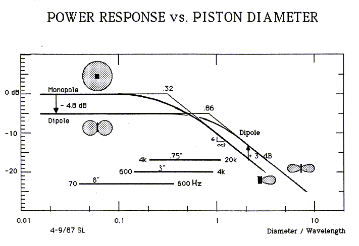
                                          I've also been trying to digest this diagram from Linkwitz:

                                          Comment

                                          • rc white
                                            Senior Member
                                            • Nov 2007
                                            • 111

                                            #22
                                            That calculation is correct.
                                            As you can see from that chart a dipole extends the region over which power response is constant, and totally flat power response needs a speaker that is totally omni directional at all frequencies, or make use of such things as phased and end fire arrays if not omni directional.
                                            Most domestic constant directivity designs have a characteristic that has constant omni directional power response up to a transition frequency, a transition region, and then a definite directivity constant power response above this.
                                            rcw

                                            Comment

                                            • Saurav
                                              Super Senior Member
                                              • Dec 2004
                                              • 1166

                                              #23
                                              Most domestic constant directivity designs have a characteristic that has constant omni directional power response up to a transition frequency, a transition region, and then a definite directivity constant power response above this.
                                              Thanks. Let's see if I understand that. I'll have a dipole woofer and midrange, with a crossover frequency (if I do it right) above the point where the midrange is still radiating into 4pi on the chosen baffle width. So my radiation pattern will be dipole up to the woofer-mid XO frequency, then start narrowing. Since I have a 90x40 waveguide, I want to cross to the tweeter at (or close to) the frequency where the angle = 45 for the midrange (assuming that's a suitable XO point). Then my dispersion stays at 90 degrees (and the power response is correct if I EQ it right), until we get to a frequency where the compression driver's response starts to narrow, and the waveguide can no longer 'hold' the dispersion to its walls (and there's really not much I can do about that short of using another supertweeter).

                                              Hopefully I got that at least partially right. And I don't really understand how the baffle width plays into the power response / driver diameter relationship. I have a vague notion that if the baffle is too wide, then the response stops being a dipole at too low a frequency. But... what happens above that frequency? It's not a monopole, is it, since there's still the rear wave from the driver.

                                              Anyway... calculating backwards, if angle = 45, then lambda = 45/58*5.23 = 4.06, which gives me a frequency of 3.3kHz. That's higher than I'd like to cross... and it's definitely past the point where my midrange is pistonic, so these simple equations probably don't really apply any more. 2kHz gives me 75 degrees, which isn't too far off. And by this point I should probably be relying on measurements to pick the XO point.

                                              Thanks once again for explaining all this.

                                              Comment

                                              • Dennis H
                                                Ultra Senior Member
                                                • Aug 2002
                                                • 3798

                                                #24
                                                I hadn't seen that diagram from SL. Pretty nifty. I rotated it and pasted in some log gridlines to make it easier (for me) to read.

                                                Following up on the dipoles for dummies thread, it looks like we have two useful rules of thumb for a full-range, multi-driver dipole if you want even power response all the way up.

                                                For each driver:
                                                1. Baffle width < (2 * cone diameter)
                                                2. Cone diameter < (.8 * wavelength at highest freq)

                                                Attached Files

                                                Comment

                                                • Dennis H
                                                  Ultra Senior Member
                                                  • Aug 2002
                                                  • 3798

                                                  #25
                                                  Saurav, I don't think Art's monopole directivity equation is too useful for an open baffle. As SL's diagram shows, monopole and dipole behavior are very different. Assuming you are operating in the flat part of the dipole curve, SL's formula for off-axis dipole SPL would be more appropriate.

                                                  dB SPL = 20 * log(cos(alpha))
                                                  alpha is angle off axis

                                                  That works out to about 1 dB down at 30 degrees, 3dB down at 45 degrees and 6 dB down at 60 degrees. Note that it's just comparing on-axis to off-axis at the same frequency. It doesn't include the dipole rolloff as frequency goes lower.

                                                  Comment

                                                  • Saurav
                                                    Super Senior Member
                                                    • Dec 2004
                                                    • 1166

                                                    #26
                                                    Do you have a link to where he discusses this on his site? And maybe I'm misunderstanding this, but it doesn't look like that formula takes driver directivity into account?

                                                    Also, what's the basis for the .8 * diameter guideline you mentioned above? Your diagram is much more readable, but I still don't think I fully grasp what it's saying

                                                    Comment

                                                    • Dennis H
                                                      Ultra Senior Member
                                                      • Aug 2002
                                                      • 3798

                                                      #27
                                                      Look at the dipole curve. It's showing the effect of driver size on power response (meaning measuring around a complete sphere and averaging) assuming perfect dipole behavior. It's perfectly flat up to diameter/wavelength = .4 and still not bad at d/w = .8. After that it rolls off fast meaning the driver is beaming and the power response is decreasing.

                                                      So, as a rough approximation, let's say your 6.5" mid has a 5" cone and you're crossing at 2K (6.8" wavelength). The ratio is about .7 so you can look on the chart and see the dipole power response isn't down much at .7 and you can guestimate that it's behaving pretty much like a pure dipole and not beaming too much at 2K.

                                                      Where did you find that pic? That's probably where he discusses it.

                                                      Edit: follow the curved lines on the chart. Those are his actual calcs of power response. Then he just extended the straight sections to show where they intersect.

                                                      Comment

                                                      • Saurav
                                                        Super Senior Member
                                                        • Dec 2004
                                                        • 1166

                                                        #28
                                                        Where did you find that pic?
                                                        Don't remember Probably somewhere in the FAQ.

                                                        It's perfectly flat up to diameter/wavelength = .4 and still not bad at d/w = .8.
                                                        OK, I wanted to be sure there wasn't anything more significant about the .8 number than that.

                                                        I'll have a compression tweeter on a waveguide, so I think I should be trying to cross to the tweeter at a frequency where the midrange's dispersion matches the waveguide's, right? Which is probably the transition region rcw was referring to - the power response drops from the dipole pattern to the tweeter's pattern, and is then constant up to the point where the WG can maintain directivity.

                                                        So, I dunno... maybe the .8 applies more for the case of crossing to a regular dome tweeter? Or there's probably something here that I'm still missing.

                                                        Actually, I am. Power response is all around the driver, while the waveguide's dispersion is only in the front. So if I cross at a frequency where the front dispersion matches, then I'll have a sharp drop in power response, right, as the rear lobe of the midrange driver drops off? Whereas if I cross higher, so the front+back of the midrange matches the front-only of the WG... I guess that's trading power response against off-axis response.

                                                        So maybe now I'm finally starting to understand the quote I started this thread with, and the difference between power response and polar radiation.

                                                        Comment

                                                        • Dennis H
                                                          Ultra Senior Member
                                                          • Aug 2002
                                                          • 3798

                                                          #29
                                                          So, I dunno... maybe the .8 applies more for the case of crossing to a regular dome tweeter?
                                                          Actually, I was thinking of a dipole tweeter. Any way you cut it, crossing a dipole to a dome or a horn is going to have a really mucked up power response unless you put another dome or horn on the back. But lots of people do that and like the sound so what the heck?

                                                          Comment

                                                          • Saurav
                                                            Super Senior Member
                                                            • Dec 2004
                                                            • 1166

                                                            #30
                                                            Heh. If you knew what I 'designed' the last time round, and was quite happy with for a few years... yes, absolutely.

                                                            Comment

                                                            • Saurav
                                                              Super Senior Member
                                                              • Dec 2004
                                                              • 1166

                                                              #31
                                                              Any way you cut it, crossing a dipole to a dome or a horn is going to have a really mucked up power response unless you put another dome or horn on the back.
                                                              Thinking about this some more... what about putting some kind of foam or polyester batting behind the midrange driver, and fiddling with it while taking measurements. The goal would be to start attenuating the rear HF response of the midrange before the crossover point. This way maybe the response in the back will fall off more smoothly, instead of being almost flat up to the XO point, and then dropping off at LR4 or whatever. So the dispersion goes from dipole in the bass, through cardoid-ish in the upper midrange, to the WG in the treble. Still not great, but maybe better than a sharp mismatch at the crossover frequency?

                                                              Someone recently mentioned doing something like this, I think, in another thread.

                                                              The trick (for me, aesthetically) will be attaching the foam to the back of an open baffle.

                                                              Comment

                                                              • augerpro
                                                                Super Senior Member
                                                                • Aug 2006
                                                                • 1867

                                                                #32
                                                                If you try to damp your mid I think the power response will be the same whether it's cardioid or dipole, the only difference is the polar response. Since one of the strengths of the dipole is the reduction of sidewall reflections (traded for delayed-but more acceptable-front wall reflections), going with a cardioid defeats that. I would think in the midrange and treble this would be undesirable? Also directivity would not match the CD as well I don't think.
                                                                ~Brandon 8O
                                                                Please donate to my Waveguides for CNC and 3D Printing Project!!
                                                                Please donate to my Monster Box Construction Methods Project!!
                                                                DriverVault
                                                                Soma Sonus

                                                                Comment

                                                                • Saurav
                                                                  Super Senior Member
                                                                  • Dec 2004
                                                                  • 1166

                                                                  #33
                                                                  Hmm, good point. I was thinking about something that only damped the upper end of the midrange's response, where presumably the dispersion has already narrowed. But that may cause more harm than good. Especially since no commercial dipole design does anything like that.

                                                                  Comment

                                                                  Working...
                                                                  Searching...Please wait.
                                                                  An unexpected error was returned: 'Your submission could not be processed because you have logged in since the previous page was loaded.

                                                                  Please push the back button and reload the previous window.'
                                                                  An unexpected error was returned: 'Your submission could not be processed because the token has expired.

                                                                  Please push the back button and reload the previous window.'
                                                                  An internal error has occurred and the module cannot be displayed.
                                                                  There are no results that meet this criteria.
                                                                  Search Result for "|||"