L pad question

Collapse
This topic is closed.
X
X
 
  • Time
  • Show
Clear All
new posts
  • Dennis H
    Ultra Senior Member
    • Aug 2002
    • 3798

    #46
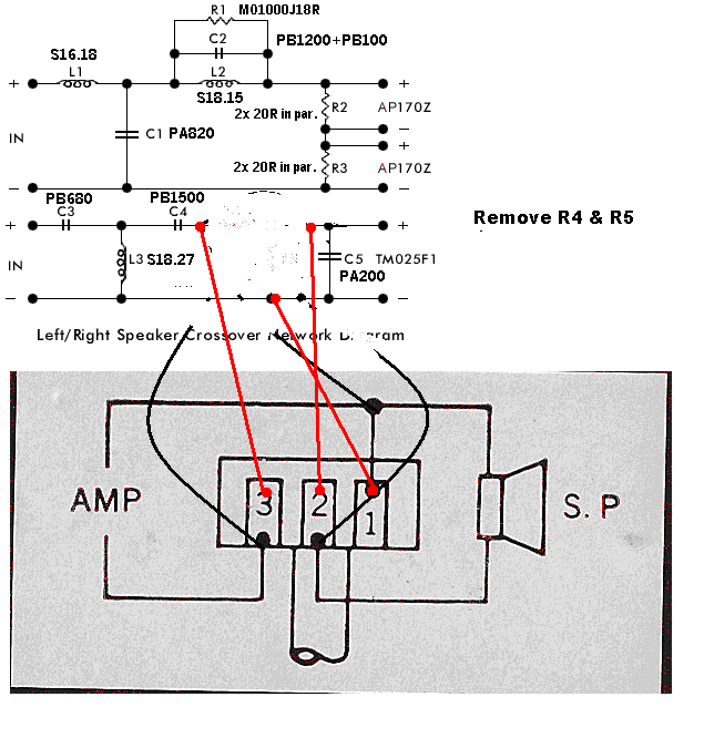
    Okay, I got out my handy eraser to make things more clear. Hook it up like this and dial it in. Then remove the lpad from the circuit and measure the values with an ohmmeter.

    Series (R4) is tab 2 to tab 3
    Shunt (R5) is tab 2 to tab 1
    Attached Files

    Comment

    • bluewizard
      Senior Member
      • Mar 2008
      • 104

      #47
      Ahhh! Sorry, I misinterpreted the image. I thought the Pin 1, Pin 2, Pin 3 was an additional part of the schematic indicating the physical crossover circuit board. In other words, pin 1,2,3 were the contact points that you soldered to on the crossover circuit board.

      Now I see that pin 1,2,3 are the pins on the L-Pad. So, I was mistaken about Dennis's drawing. It is right, but I think mechanically, it is better to remove R4/R5 and put a jumper wire in place of R4. Then connect the L-Pad between the crossover and the speaker as shown in my last drawing.

      Still for a quick and easy test, you could lift one end of each R4/R5 to take them functionally out of the circuit, then clip the L-Pad in as Dennis shows.

      Can't believe I didn't see that diagram for what it was.

      Steve/bluewizard (who was simultaneously right and wrong, and with apologies to Dennis)
      Last edited by bluewizard; 12 March 2008, 18:45 Wednesday.

      Comment

      • ThomasW
        Moderator Emeritus
        • Aug 2000
        • 10933

        #48

        IB subwoofer FAQ page


        "Complicated equipment and light reflectors and various other items of hardware are enough, to my mind, to prevent the birdie from coming out." ...... Henri Cartier-Bresson

        Comment

        • Dennis H
          Ultra Senior Member
          • Aug 2002
          • 3798

          #49
          I think mechanically, it is better to remove R4/R5 and put a jumper wire in place of R4. Then connect the L-Pad between the crossover and the speaker as shown in my last drawning.
          Nope. R4 has to be before C5 to keep the original electrical signal path and hopefully not muck things too badly by changing values. If R4 were after C5, the amp would see a dead short to ground at high frequencies.

          Edit: Yikes, Danger Will Robinson!! Dean, do not turn the L-pad all the way up when you're testing. If R4 goes to 0 ohms, your amp will see a 0 ohm load at high frequencies and may let out its magic smoke. Be very, very careful. Before you put the L-pad in, find the knob position where the resistance between tabs 2 and 3 is 2 ohms and don't ever turn it above there. Since you're trying to cut highs rather than boost them, there is no reason to ever turn it up that high.

          Comment

          • bluewizard
            Senior Member
            • Mar 2008
            • 104

            #50
            Dennis,

            Are you saying that because of C5 being in the circuit or because of the action of the L-Pad. C5 will certainly go to an AC short at high frequencies, but that would be extremely high frequencies. Assuming this tweeter goes up to 20khz, C5 is probably moderating some bump in the frequency response that occurs in the 15khz range. So, in that sense you may be on to something, but it is likely to have a 6db slope which means it will take several octaves to get down near zero.

            Still, it is something to consider.

            As to the L-Pad, when it is turned all the way down, the 8 ohm side is in parallel with the amp and the tweeter is shorted to ground. When it is all the way up, the wiper or Pin 2 is connected directly to the input and Pin 2-1 is a 600ohm resistor to ground.

            In this last case, C5 could at very high frequencies be an AC short to ground. By 'AC short' I mean the signal would be shorted, but it the amp wouldn't see a direct DC short to ground.

            For a permanent solution, I would recommend R5 which would be a 4 to 8 ohms resistor placed as shown in the lower diagram.

            These things are never easy.

            Steve/bluewizard
            Attached Files

            Comment

            • Dennis H
              Ultra Senior Member
              • Aug 2002
              • 3798

              #51
              If you want to redesign the crossover by doing things like putting resistors in series with caps, that's certainly okay. All you need is measurements of the drivers in the baffle and then plug it all into crossover design software and see what you get.

              Otherwise, just don't turn the L-pad up too high while you're finding the values of the fixed resistors so your amp doesn't (maybe, depends on the amp) go into an HF oscillation and let its magic smoke out. The magic smoke is what makes them run and you have to keep it inside the box.

              Edit: Sorry, that sounds condescending. Magic smoke is an old inside joke here at HTG.

              Comment

              • bluewizard
                Senior Member
                • Mar 2008
                • 104

                #52
                Well, if the Cap (C5) is marked with its value, you can simply find out at what frequency the Cap is the same as the speaker, and that is likely the crossover point for that Cap.

                And for the record, I wasn't so much disagreeing with you as expanding and clarifying the point you made. While I don't think it is quite as bad as you're making it out, it is still a very dicey situation, and one that needs to be dealt with. At some frequency C5 is going to be near zero, and that has the potential for problems.

                Since C5 always had a 4 ohm resistor in series with it, it seems a safe bet placing one literally in series with it would be OK.

                I won't concede that Magic Smoke will exist, only that the potential for it to exist is very real.

                So, as a safe bet, follow Dennis's advice, start with the L-Pad in the middle and restrain yourself from going full volume on the tweeter until you have done something to make C5 safe.

                Again, I say just install the L-Pad permanently, add 4 ohms, as you have a 4 ohm resistor handy, to C5, and you should be good to go.

                Hey...I'm just saying.

                Steve/bluewizard

                Comment

                • DeanP
                  Senior Member
                  • May 2004
                  • 175

                  #53
                  Well, well, well; I am going to wire just like post #46 and I will keep it half way and watch what how much I turn it up. Probably start this weekend.
                  Thanks for the help so far. :T

                  Comment

                  • DeanP
                    Senior Member
                    • May 2004
                    • 175

                    #54
                    Well, I decided only to install L-pads on the mains because I didn't want to mess with the center as it is good for HT.
                    Installation went well.
                    Now for testing them out...I set them up at halfway and then neutraled my reciever. At the end, the L-pads were about 1/4 turned up (~ 6 ohms) and I turned up my reciever to compensate if I needed to make them brighter.

                    Now I am wondering if I should set my reciever' treble to full value, neutral or full off and then adjust the L-pad to best "listening". I guessing I did it correctly at neutral.

                    I am liking the idea of leaving them in place but I need to know how to so if it gets turned up for better "sound". If I get a new reciever, which is on the "not so bright side", I would like to be able to set them up easier than temp. installing L-pads, doing measurements ect.
                    Ideas? for all that what was said...

                    Comment

                    • ThomasW
                      Moderator Emeritus
                      • Aug 2000
                      • 10933

                      #55
                      The L-pad is simply attenuating (decreasing) the amount of signal going to the tweeter. Once it's in the signal path turning it up or down has minimal impact on the sound quality

                      Using EQ to boost the treble attenuated by the L-pad, means you have the effect of the distortion in the EQ electronics in addition to the effect of the L-pad.

                      I don't understand why anyone would want to do that....

                      IB subwoofer FAQ page


                      "Complicated equipment and light reflectors and various other items of hardware are enough, to my mind, to prevent the birdie from coming out." ...... Henri Cartier-Bresson

                      Comment

                      • DeanP
                        Senior Member
                        • May 2004
                        • 175

                        #56
                        Okay, I guess it would be better to remove the l-pad and replace it with resistors. (I'll order the resistors in my next order unless I have the correct resistor values around here)
                        So in other words, I should set my reciever to neutral and set the L-pad so it sounds best to me. Then I'll remove it from the speaker and measure it.
                        I'm guessing that the series will be about 6 ohms and the shunt about 10 ohms because when I measured it before at center it was 4 ohm and 15 ohms.
                        Thanks everone for all the help! :T

                        Comment

                        Working...
                        Searching...Please wait.
                        An unexpected error was returned: 'Your submission could not be processed because you have logged in since the previous page was loaded.

                        Please push the back button and reload the previous window.'
                        An unexpected error was returned: 'Your submission could not be processed because the token has expired.

                        Please push the back button and reload the previous window.'
                        An internal error has occurred and the module cannot be displayed.
                        There are no results that meet this criteria.
                        Search Result for "|||"