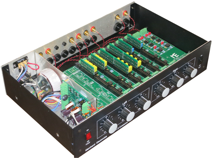
DIY active x-over for 2.1 application

Collapse
This topic is closed.
X
X
 
  • Time
  • Show
Clear All
new posts
  • peter_m
    Senior Member
    • Sep 2007
    • 227

    DIY active x-over for 2.1 application

    Hi all,

    I am looking for an active crossover, like the ones you find in the average HT amp. With a variable frequency from 40 to 200hz. I need it to have both high-pass and low-pass outputs. This way I can re-use existing amps I have lying around for a 2.1 project.

    Any chance of you guys seeing an inexpensive DIY design floating out there?

    Peter
  • ThomasW
    Moderator Emeritus
    • Aug 2000
    • 10933

    #2
    Here's the deal, you can certainly find something to build, But I doubt it will sound any better or be built for less than one of the Behringer units. CX2310 or CX3400.

    I have numerous Marchand XM-9 kits, these are fairly spendy in comparison to either of the Behringers. And what's frustrating for me is I can't hear a difference between my modded XM-9's and the Behringers...

    IB subwoofer FAQ page


    "Complicated equipment and light reflectors and various other items of hardware are enough, to my mind, to prevent the birdie from coming out." ...... Henri Cartier-Bresson

    Comment

    • peter_m
      Senior Member
      • Sep 2007
      • 227

      #3
      Wow, Thomas... you flatter me. Didn't you know I was cheep!! :P

      Seriously, that's out of my budget and a little large. I really was looking for something to tinker with during the crazy holiday season... you know, to have an excuse to hide from drunk family member when they come over.

      Comment

      • Dennis H
        Ultra Senior Member
        • Aug 2002
        • 3798

        #4
        $90 is out of your budget? I seriously doubt you can build anything for less by the time you gather all the bits and pieces. Read one of the Marchand manuals for a list of everthing you will need. You can use cheaper parts than Marchand does but you'll still need all the parts.

        Comment

        • chasw98
          Super Senior Member
          • Jan 2006
          • 1360

          #5
          You can build an active crossover using 2 NE5532 op amps for $2.00 and about 4 resistors and 4 capacitors that will cost you maybe another $2.00. But you will have to power this active unit with a bipolar DC supply, usually 15 volts unless you tap off an existing supply in a unit you already own. To make it adjustable splurge and buy 5 or 6 sets of resistors and capacitors in different values and substitute them in the circuit! Otherwise the Behringer crossovers are the best cheapest alternative.

          Comment

          • peter_m
            Senior Member
            • Sep 2007
            • 227

            #6
            Chasw98,
            can you elaborate on the "bipolar DC supply"? What makes it different than a conventional PSU?

            Peter

            Comment

            • chasw98
              Super Senior Member
              • Jan 2006
              • 1360

              #7
              A bipolar supply can have plus and minus of a given voltage. Such as +15 Volts and
              -15 volts. Usually they share a common ground.

              Comment

              • ThomasW
                Moderator Emeritus
                • Aug 2000
                • 10933

                #8
                AFAIK, this is the lowest cost 'dual' PS on the planet. It's about $18 delivered.
                an ideal place for the maker, hobbyists, model builders, audiophiles, artists, and the do-it-yourself electronic enthusiast. We feature electronic parts, electrical supplies, hardware, wire and cable, test equipment, and thousands of hard to find items.


                You'll need a chassis so figure $30 for it. Couple bucks for a power cord. You'll also need, fuse holder, RCA jacks, breadboard or PCB $5-$10, rubber feet, PCB stand-off hardware, op-amps, caps, resistors, wire, solder.

                The places that sell the above hardware have a $25 min. Add that to the cost of the power supply, the chassis and....realistically there's no way to make a completed crossover for much less than the cost of a CX2310

                IB subwoofer FAQ page


                "Complicated equipment and light reflectors and various other items of hardware are enough, to my mind, to prevent the birdie from coming out." ...... Henri Cartier-Bresson

                Comment

                • pedroskova
                  Member
                  • Mar 2007
                  • 38

                  #9
                  Hi: first post(I think)...

                  Peter_M may not need all of these things, but I'll play devil's advocate anyway.

                  He may need the following that the CX2310 doesn't provide:

                  single-ended inputs/outputs
                  low/high shelving / Linkwitz transform
                  1st, 2nd, 3rd order slopes in any combination
                  asymmetrical slopes
                  notch filters

                  ...and a chassis that isn't so...aesthetically challenged.

                  Comment

                  • Davey
                    Senior Member
                    • Jan 2003
                    • 355

                    #10
                    Peter,

                    What...exactly...is it you're trying to do? I think Thomas is correct...the Behringer CX2310 sounds like the perfect option, and it's pretty cheap. It's fun to tinker....but your time is money too.

                    Shop for Guitars, Drums, Amplifiers and Equipment from Same Day Music! Get the best price, fastest shipping and tech support from our incredibly knowledgeable sales team.


                    You say you want a variable crossover frequency. You say "2.1" (summed low-pass channel.) You can do both of those things (and all the things pedroskova mentioned) with a DIY unit, but it's going to get complicated. No offense, but, this might be a challenging project for a fella who doesn't know what a bipolar power supply is.

                    I'd buy the CX2310 and be done with it.

                    Dave.

                    Comment

                    • ThomasW
                      Moderator Emeritus
                      • Aug 2000
                      • 10933

                      #11

                      IB subwoofer FAQ page


                      "Complicated equipment and light reflectors and various other items of hardware are enough, to my mind, to prevent the birdie from coming out." ...... Henri Cartier-Bresson

                      Comment

                      • peter_m
                        Senior Member
                        • Sep 2007
                        • 227

                        #12
                        Originally posted by ThomasW
                        Add that to the cost of the power supply, the chassis and....realistically there's no way to make a completed crossover for much less than the cost of a CX2310
                        Originally posted by Davey
                        Peter,

                        What...exactly...is it you're trying to do? I think Thomas is correct...the Behringer CX2310 sounds like the perfect option, and it's pretty cheap. It's fun to tinker....but your time is money too.
                        No offence to anyone who was generous of his time and posted opinions in this thread... really, I appreciated variety and differences! But I want to do it my self because I get a kick out of doing things my self. I see it as a challenge/brain exercise... some might say I have something to prove to my self... I don't really care. As a bonus, I usually end up learning something and I get to say... "I made that!".

                        All in all it's like someone sitting in the bus filing out a cross word puzzle... Does he care that it will end-up in a recycling bin or that he could pickup a news paper left on the bus bench for free and with the crossword puzzle completed... Who cares, it's just for the fun of doing it...

                        Regards,

                        Peter


                        PS:
                        Originally posted by Davey
                        No offense, but, this might be a challenging project for a fella who doesn't know what a bipolar power supply is.
                        That does offend me somewhat but who cares... I'm still gonna give it a shot! :W

                        PPS: I am not masochistic but I do live within walking distance form an electronics surplus warehouse and I'm within driving distance from Solen.ca... 8)

                        Comment

                        • Davey
                          Senior Member
                          • Jan 2003
                          • 355

                          #13
                          Excellent.

                          There are a number of customizable active crossover kits available. I think Rod Elliot's PC boards and power supply kit would be a good place to start:


                          Dave.

                          Comment

                          • ThomasW
                            Moderator Emeritus
                            • Aug 2000
                            • 10933

                            #14
                            Have fun.....and good luck...


                            Bob Ellis' group buy PCB


                            IB subwoofer FAQ page


                            "Complicated equipment and light reflectors and various other items of hardware are enough, to my mind, to prevent the birdie from coming out." ...... Henri Cartier-Bresson

                            Comment

                            • chasw98
                              Super Senior Member
                              • Jan 2006
                              • 1360

                              #15
                              Originally posted by peter_m
                              PPS: I am not masochistic but I do live within walking distance form an electronics surplus warehouse and I'm within driving distance from Solen.ca... 8)
                              Well, then Peter. Here is what I would do to start and get your feet wet to see if you want to go further.
                              1) Don't worry about a case or enclosure right now.
                              2) Buy the skycraft power supply. Best and cheapest there is (and it will be very hard to blow it up even if you short it)
                              3) Buy a breadboard kit that will allow you to mount IC's and components on it so that you may wire a circuit and see what it will do.
                              4) Go look at Rod Elliots or Marchands site for schematics and buy a handful of components and assemble them on the breadboard, hook up the power supply, blow it up the first time because of crossed wires (parts are cheap so this is part of the learning curve) and then get it to work!
                              5) Start experimenting now that you have built a working prototype.
                              6) Post back here with pictures and progress.

                              Chuck

                              Comment

                              • Habs4life
                                Member
                                • Apr 2006
                                • 85

                                #16
                                If you are going the DIY route the Bob Ellis boards are excellent but I believe are unobtainable, so I think the next best choice though pricey is the Linkwitz MT1 board. http://www.linkwitzlab.com/pcb.htm As well as the filter sections you can also incorporate time delay for the tweeter and baffle step compensation.Both channels are on a single board.

                                Edit.Ofcourse you won't need the delay or BSC for your 2.1 set up,but if in the future you want to try an active 2 way, you will have the capability to easily add these important elements.
                                Last edited by Habs4life; 15 December 2007, 14:45 Saturday.

                                Comment

                                • peter_m
                                  Senior Member
                                  • Sep 2007
                                  • 227

                                  #17
                                  On the Linkwitz site, there is a spreadsheet that I can use to adjust the desired cut-off frequency by calculating the R value for a given C value.... Do I have any restrictions on the C values? Any reason to go higher or lower? The default value in the spreadsheet was 15uF.... Also what type of capacitor should I get?

                                  Peter

                                  Ref:

                                  Comment

                                  • chasw98
                                    Super Senior Member
                                    • Jan 2006
                                    • 1360

                                    #18
                                    Go here http://www.marchandelec.com/xm1.html and then read the manual for the crossover here http://www.marchandelec.com/ftp/xm1man.pdf . The parts list in Table 1 will tell you what kind of parts to look for metal film resistors, polypropylene capacitors. Familiarize your self with this and if you read the whole manual, Phil will tell you what some guidelines are as to values to keep in range of when you start figuring out capacitor and resistor values for a crossover point.

                                    Comment

                                    • Davey
                                      Senior Member
                                      • Jan 2003
                                      • 355

                                      #19
                                      Peter,

                                      The default value in the sheet is 15n(ano)F, not 15 uF. That's .015uF and should yield nominal resistor values. I don't think I'd use a capacitor value any lower than that. Somewhere in the 10-100nF range is good.

                                      Polypro capacitors are ideal for this usage. Check in the Digikey catalog for Panasonic P-series and you'll see a terrific selection. Use 1% metal film resistors.

                                      Dave.

                                      Comment

                                      • jeff_free69
                                        Member
                                        • Dec 2007
                                        • 74

                                        #20
                                        Do you guys really like behringer??

                                        This may be an unfounded statement since ive never tried their active crossover, but in the pro-audio world , behringer is pretty much considered the bottom of the barrel.

                                        Some people really despise them if for no other reason than because they copy everything from other manufacturers and build it extremely really cheaply.

                                        if you're just looking to experiment fine, but it seems everybody on this board would have a higher standard.

                                        Comment

                                        • chasw98
                                          Super Senior Member
                                          • Jan 2006
                                          • 1360

                                          #21
                                          Originally posted by jeff_free69
                                          This may be an unfounded statement since ive never tried their active crossover, but in the pro-audio world , behringer is pretty much considered the bottom of the barrel.

                                          Some people really despise them if for no other reason than because they copy everything from other manufacturers and build it extremely really cheaply.

                                          if you're just looking to experiment fine, but it seems everybody on this board would have a higher standard.
                                          If the units are not being trucked around in rack cases from city to city every night and schlepped by hired hands higher than a kite, then you are right Behringer is awful. But if it is going to be used in your heated and cooled environment friendly living room, that is different. As far as specs and fidelity go, they are equal if not better than most of the names out there at a much more reasonable price. A lot of people have compared the DBX drive racks to the DCX 2496 and liked the 2496 better. That is not to say that you cannot spend a lot more bucks and get better, but for what it is, it is very good.

                                          PS, they used to copy others and build cheaply. They got bit doing that and now they have some very well built units.

                                          Comment

                                          • ThomasW
                                            Moderator Emeritus
                                            • Aug 2000
                                            • 10933

                                            #22
                                            Having compared the Behringer analog units to some costing many times more, I'll offer the following....

                                            When used in an average 'mid-fi' system, the analog crossovers are so good as to be sonically invisible. In a system with high-end electronics and speakers, the Behringers are as transparent as units costing 5+ times more money.

                                            Whether anyone decides to buy Behringer is between them and their conscious, (vote with your wallet as they say)

                                            IB subwoofer FAQ page


                                            "Complicated equipment and light reflectors and various other items of hardware are enough, to my mind, to prevent the birdie from coming out." ...... Henri Cartier-Bresson

                                            Comment

                                            • peter_m
                                              Senior Member
                                              • Sep 2007
                                              • 227

                                              #23
                                              ROFLOL!!!!

                                              No more then 6 hours after I ordered from Digikey, I find exactly what I was looking for in a different thread:

                                              And it only costs about 10 or 15$ more then the parts I ordered... and it comes in a nice enclosure with nice knobs to adjust and re-adjust as I might have seen fit... ARG! Oh well, I guess I will just have to continue what I started.

                                              LOL, I feel like a DIY fool!

                                              Peter

                                              Comment

                                              • Habs4life
                                                Member
                                                • Apr 2006
                                                • 85

                                                #24
                                                Originally posted by peter_m
                                                .. I feel like a DIY fool!
                                                You shouldn't because the fun and knowledge gained by building from scratch will be worth it.

                                                Comment

                                                • peter_m
                                                  Senior Member
                                                  • Sep 2007
                                                  • 227

                                                  #25
                                                  Thanks Habs4life,

                                                  I know I will learn, also enjoy the "I saved 50$" but this time I will only save 10$ LOL. But it's not in vain as I found the F-1 is less then perfect and not exactly up to the advertised specs: http://www.hometheatershack.com/foru...fications.html

                                                  I feel better now!

                                                  PS: Habs vs Nordiques, or Habs vs Boston in the 70s and early 80s.... were the last times I watched a real hockey game... sad!

                                                  Comment

                                                  • Habs4life
                                                    Member
                                                    • Apr 2006
                                                    • 85

                                                    #26
                                                    Originally posted by peter_m


                                                    PS: Habs vs Nordiques, or Habs vs Boston in the 70s and early 80s.... were the last times I watched a real hockey game... sad!
                                                    Yes there was some great rivalries between those teams back then.


                                                    good luck with your project Peter.

                                                    Comment

                                                    • peter_m
                                                      Senior Member
                                                      • Sep 2007
                                                      • 227

                                                      #27
                                                      Ok so the crossover works now.... Let's give credit where it is due... Thank you all for submitting advice and ideas... I have to admit I was a little discouraged when I first powered up the power supply and I saw spark going all over the PCB board... I started to remember your advice ThomasW :P . The darn thing had traces too close together and I had to scratch off some copper to have wider gaps between some of the traces... the caps kept discharging randomly in about 6 different places. In hind sigh it was funny cause it looked like a cheap special effect like you would see in the 80s. I guess that's what I get for a 0.99$ PCB. Lucky nothing fried...

                                                      So far it has cost me about 55$ CAD without a case for now. I used this for the PSU: http://sound.westhost.com/project05.htm

                                                      And this for the filter: http://www.linkwitzlab.com/filters.htm#3

                                                      Does anyone know if I should use a input buffer? Also can an input buffer be used to compensate for low source? For example I was using an old CD player as a test source and it played considerably lower then my iPod. Can I do something to manually adjust when ever I change my source?

                                                      PS: I't a little late to crank it up but as far as I can tell, no hum or ground loop problems.... for now!

                                                      Comment

                                                      • chasw98
                                                        Super Senior Member
                                                        • Jan 2006
                                                        • 1360

                                                        #28
                                                        Originally posted by peter_m
                                                        Ok so the crossover works now.... Let's give credit where it is due... Thank you all for submitting advice and ideas... I have to admit I was a little discouraged when I first powered up the power supply and I saw spark going all over the PCB board... I started to remember your advice ThomasW :P . The darn thing had traces too close together and I had to scratch off some copper to have wider gaps between some of the traces... the caps kept discharging randomly in about 6 different places. In hind sigh it was funny cause it looked like a cheap special effect like you would see in the 80s. I guess that's what I get for a 0.99$ PCB. Lucky nothing fried...

                                                        So far it has cost me about 55$ CAD without a case for now. I used this for the PSU: http://sound.westhost.com/project05.htm

                                                        And this for the filter: http://www.linkwitzlab.com/filters.htm#3

                                                        Does anyone know if I should use a input buffer? Also can an input buffer be used to compensate for low source? For example I was using an old CD player as a test source and it played considerably lower then my iPod. Can I do something to manually adjust when ever I change my source?

                                                        PS: I't a little late to crank it up but as far as I can tell, no hum or ground loop problems.... for now!
                                                        First off, the Golden Rule. No pictures, No project :B Let's see some pictures, especially if you got sparks!

                                                        An input buffer is just usually an IC op amp and you can control the gain of the op amp with a resistor or even a variable resistor, so yes it can be handy to put one in.

                                                        Chuck

                                                        Comment

                                                        • Habs4life
                                                          Member
                                                          • Apr 2006
                                                          • 85

                                                          #29
                                                          Congrats on a successfull build.
                                                          If you are using that filter circuit as shown then it really should have a buffer in front of it so as to isolate the filter components from the source.You can make the buffer have unity gain( no gain) or have as much gain as you need.You can also install a pot for adjustability.

                                                          Comment

                                                          • peter_m
                                                            Senior Member
                                                            • Sep 2007
                                                            • 227

                                                            #30
                                                            Here are the pictures requested. Please imagine the sparks running randomly along the traces highlighted in red.... it was discouraging at first but all I needed was a magnifier and an Xact-O to fix the problem. All the resistors and capacitors are 2% tolerance... just to save a few buck... OK maybe 1$ at the most. I used bypass caps for all the V+ and V- inputs on the LM2134. 10nF ceramics is what I used and kept the distance between chip and cap as short as possible. I used the bottom half of the LM2134 for High pass and the top half for the low pass. X-over frequency is fixed at 150hz.

                                                            NOTE: THERE IS NO HUM AT ALL! This thing is dead quiet! :twisted:

                                                            I will add gain control/input buffer for the inputs and maybe a gain contron for the combined L-R low pass output.
                                                            Attached Files
                                                            Last edited by peter_m; 09 January 2008, 16:45 Wednesday.

                                                            Comment

                                                            • CFC
                                                              Junior Member
                                                              • Dec 2007
                                                              • 9

                                                              #31
                                                              I hope I'm not imposing too much by asking this question on this thread.
                                                              I'm looking to build a mono version of this preamp on ESP ( #88 ) http://sound.westhost.com/project88.htm
                                                              How should I modify the volume control circuit (Figure 3 on the page) to eliminate the balance control? I'm not that familiar with using pots.
                                                              Is this a good preamp to build? I'm hoping to use it with a subwoofer amp that does not currently have gain control but has +/- 15V rails available in its enclosure. This would be a one chip solution and relatively small, so I thought I'd give it a shot.

                                                              Thanks for the help,
                                                              CFC

                                                              Comment

                                                              • Dennis H
                                                                Ultra Senior Member
                                                                • Aug 2002
                                                                • 3798

                                                                #32
                                                                Rod says "If you don't want to use the balance pot, it may be left out of the circuit entirely." So the volume pot between the gain stages would be wired like this. Make sure you get a linear pot, not one with a log taper.

                                                                Attached Files

                                                                Comment

                                                                • BobEllis
                                                                  Super Senior Member
                                                                  • Dec 2005
                                                                  • 1609

                                                                  #33
                                                                  As shown above, a log pot is appropriate.

                                                                  You'd only use a linear taper pot if you're using his law faking setup with a resistor from AL to BL.

                                                                  Comment

                                                                  • Dennis H
                                                                    Ultra Senior Member
                                                                    • Aug 2002
                                                                    • 3798

                                                                    #34
                                                                    Originally posted by BobEllis
                                                                    As shown above, a log pot is appropriate.

                                                                    You'd only use a linear taper pot if you're using his law faking setup with a resistor from AL to BL.
                                                                    Bob, correct me if I'm wrong, but I thought the resistor to turn a linear pot into a quasi-log pot goes on the output of the pot, from BL to ground. R6 on the input of the second gain stage appears to do that.


                                                                    Comment

                                                                    • BobEllis
                                                                      Super Senior Member
                                                                      • Dec 2005
                                                                      • 1609

                                                                      #35
                                                                      Oops. That what I get for posting while working. You're right, the law faking resistor goes wiper to ground.

                                                                      R6 above would tend to act as a law faker, but it is a rather high value compared to a reasonable pot. I'd say a 20K pot in this circuit would be fine, so a law faker would be ~4K, making the total load ~3.3K at high attenuation. That may be hard for the preceding stage to drive, but shoud be OK. The tradeoff with higher value pots is more noise. Of course you could try a 100K pot and 22K resistor for R6.

                                                                      If you use an audio taper pot AND hard wire it to point BL youcan eliminate R6. Its purpose is to ensure a DC path to ground for the +input. You'll have that with the pot.

                                                                      Lots of ways to skin the cat.

                                                                      Comment

                                                                      • IllNastyImpreza
                                                                        Member
                                                                        • Jan 2008
                                                                        • 77

                                                                        #36
                                                                        I've heard of building passives... but actives??? you my friend are BOLD

                                                                        Comment

                                                                        • CFC
                                                                          Junior Member
                                                                          • Dec 2007
                                                                          • 9

                                                                          #37
                                                                          I appreciate the help on this.
                                                                          Looking at Digi-Key, I'm getting a bit dizzy trying to find an appropriate potentiometer. Could you point me as to which I should be looking at: 0.5W? Top Adjustment? Panel Mount (I assume this is for mounting externally off the board)? Should I get a 1% tolerance like the metal film resistors?
                                                                          I'll be using polyester caps and metal film resistors with 1% tolerance.

                                                                          Comment

                                                                          • BobEllis
                                                                            Super Senior Member
                                                                            • Dec 2005
                                                                            • 1609

                                                                            #38
                                                                            Most likely you'll want a panel mount (yes, for off board mounting) so that you can adjust on the fly without opening the enclosure. You won't dissipate any power in the pot, so any power rating available in the value and package you want should be fine.

                                                                            Comment

                                                                            • Habs4life
                                                                              Member
                                                                              • Apr 2006
                                                                              • 85

                                                                              #39
                                                                              Originally posted by CFC
                                                                              I appreciate the help on this.
                                                                              Looking at Digi-Key, I'm getting a bit dizzy trying to find an appropriate potentiometer.
                                                                              The Bourns Series 91 conductive plastic pots are a good choice.

                                                                              Comment

                                                                              • CFC
                                                                                Junior Member
                                                                                • Dec 2007
                                                                                • 9

                                                                                #40
                                                                                Thanks for the recommendation, I went ahead and added to my shopping cart. I'll be sure to post a little pic once I'm done with the project (hopefully before the end of the month).

                                                                                CFC

                                                                                Comment

                                                                                • peter_m
                                                                                  Senior Member
                                                                                  • Sep 2007
                                                                                  • 227

                                                                                  #41
                                                                                  Reviving an old thread because it's relevent

                                                                                  Can anyone tell me if this is possible.

                                                                                  If I were to reproduce transfer functions such as these with OpAmps, would it perform and sound like the original passive x-over was designed to? Should I expect some surprises or difference in performance?

                                                                                  Any simple way to generate/calculate the OpAmps?

                                                                                  Peter

                                                                                  Comment

                                                                                  • IllNastyImpreza
                                                                                    Member
                                                                                    • Jan 2008
                                                                                    • 77

                                                                                    #42
                                                                                    how is the project going ?

                                                                                    Comment

                                                                                    • Deward Hastings
                                                                                      Senior Member
                                                                                      • Dec 2006
                                                                                      • 170

                                                                                      #43
                                                                                      > If I were to reproduce transfer functions . . . with OpAmps . . .

                                                                                      You could get close, but for a lot of reasons it would be difficult to exactly mimic the passive design. But that's not the best way to approach active crossover design anyway. Crossovers generally do three things: they correct driver response issues (as with notch filters); they divide the pass band (for which they are named); and they provide fixed equalization to "voice" the complete assembly and address room and placement issues (like baffle step compensation). In a "passive" design those functions are lumped together . . . the circuit topology of (analog) active crossovers treats each function separately (digital active crossovers take those functions as inputs and create a combination computationally). The basic analog boxes (from Behringer, Marchand etc.) only do the crossover function (although they do that perfectly, within their limits), leaving driver correction and equalization to be done separately. For an instructive example of an analog active crossover that includes all three functions look at the topology of the ORION asp (thoroughly described at the linkwitzlab web site).

                                                                                      Nothing prevents mixing things up . . . you can use a basic LR4 active crossover for it's function and put a passive notch filter between the amplifier and a driver that needs it. And many HT receivers will automatically insert baffle step correction for you if it's need for your placement in your room. Doing it that way (or with a "graphic equalizer") is far more flexible than baffle step correction with a passive crossover, where at best you have to break out the soldering iron, and at worst redesign the whole crossover, if you move the speaker a couple feet closer to the wall.

                                                                                      You'll build a better active crossover if instead of trying to replicate the transfer function of a passive one you do your design from scratch.

                                                                                      Comment

                                                                                      Working...
                                                                                      Searching...Please wait.
                                                                                      An unexpected error was returned: 'Your submission could not be processed because you have logged in since the previous page was loaded.

                                                                                      Please push the back button and reload the previous window.'
                                                                                      An unexpected error was returned: 'Your submission could not be processed because the token has expired.

                                                                                      Please push the back button and reload the previous window.'
                                                                                      An internal error has occurred and the module cannot be displayed.
                                                                                      There are no results that meet this criteria.
                                                                                      Search Result for "|||"