Poobahs - basket resonance?

Collapse
This topic is closed.
X
X
 
  • Time
  • Show
Clear All
new posts
  • Dennis H
    Ultra Senior Member
    • Aug 2002
    • 3791

    Poobahs - basket resonance?

    I was perusing SL's site and he has a new article on mounting drivers.


    This caught my eye:

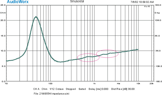
    "The basket-magnet resonance.... Often the resonance can be seen as a small bump in the driver's impedance curve in the few hundred Hz range. It should not be confused with the higher frequency bump due to cone breakup."

    Is this the source of the weird impedance glitch we see on so many Scanspeak and other drivers at around 800Hz or so? If so, that requires a paradigm shift (to quote a cliche) in evaluating drivers and what you have to do to make them work. Maybe all those drivers need is a better mounting method rather than XO tweaks, etc.?
  • JonMarsh
    Mad Max Moderator
    • Aug 2000
    • 15284

    #2
    :huh: Hint: Suspend driver by thread, tap on basket with a small rubber mallet, look at output in True RTA.

    Can do the same thing with driver mounted; then you're looking at stiffness of frame, mass of magent.

    I haven't seen a woofer basket that had a resonance below 1 kHz.

    The "giveaway" in my opinion to sepearate cone modes from other things that go bump in the night, is to measure the driver in several locations ultra near field. Typically, in dead center, near the cone edge, and say, half way between the two.

    Now, if a simple chinese made driver like the HiVi M8a can track so well up to primary cone mode at 2.4 kHz, and shows no impedance glitch below the cone breakup mode, then either they know something about baskets and surround resonance (which these glitches are often attributed to) that ScanSpeak and others don't know (unlikely), or, they have a better behaved cone (more pistonic), which my mreasurements confirm. When you see correlation between misbehavior/non-tracking of certain cone areas and the impedance glitches, I don't think it's necessary to go looking further. But may be I'm just being a luddite.

    The real mystery to me is why it seems no one else besides me and Mark K and SL measures this way... (ultra nearfield). Or why no one else except Mark and I measure at multiple cone points. :huh:

    Oh well. Maybe I'm over simplifying things. It's an Occam's razor kind of thing with me, at times.

    ~Jon
    the AudioWorx
    Natalie P
    M8ta
    Modula Neo DCC
    Modula MT XE
    Modula Xtreme
    Isiris
    Wavecor Ardent

    SMJ
    Minerva Monitor
    Calliope
    Ardent D

    In Development...
    Isiris Mk II updates- in final test stage!
    Obi-Wan
    Saint-Saëns Symphonique/AKA SMJ-40
    Modula PWB
    Calliope CC Supreme
    Natalie P Ultra
    Natalie P Supreme
    Janus BP1 Sub


    Resistance is not futile, it is Volts divided by Amperes...
    Just ask Mr. Ohm....

    Comment

    • Davey
      Senior Member
      • Jan 2003
      • 355

      #3
      Originally posted by JonMarsh

      The real mystery to me is why it seems no one else besides me and Mark K and SL measures this way... (ultra nearfield). Or why no one else except Mark and I measure at multiple cone points.

      ~Jon
      I think the answer to those questions should be obvious.

      Davey.

      Comment

      • JonMarsh
        Mad Max Moderator
        • Aug 2000
        • 15284

        #4
        As in, we're just a little touched in the head?
        the AudioWorx
        Natalie P
        M8ta
        Modula Neo DCC
        Modula MT XE
        Modula Xtreme
        Isiris
        Wavecor Ardent

        SMJ
        Minerva Monitor
        Calliope
        Ardent D

        In Development...
        Isiris Mk II updates- in final test stage!
        Obi-Wan
        Saint-Saëns Symphonique/AKA SMJ-40
        Modula PWB
        Calliope CC Supreme
        Natalie P Ultra
        Natalie P Supreme
        Janus BP1 Sub


        Resistance is not futile, it is Volts divided by Amperes...
        Just ask Mr. Ohm....

        Comment

        • AndrewM
          Senior Member
          • Oct 2000
          • 446

          #5
          Well I have a question in regards to the measuring "ultra" nearfield. When you measured the Dayton speakers that way you found that null in the response which didn't show up as the measurement moved away from the driver. Why is that? Or more importantly, if that "problem" doesn't show up away from the driver why should I consider it an issue when building a non nearfield system?

          Andrew

          Comment

          • JonMarsh
            Mad Max Moderator
            • Aug 2000
            • 15284

            #6
            Hello Andrew,

            In doing what I describe as "ultra nearfield measurements", the microphone is positioned ~ 0.5" to 1" away from the area to be measured. Due to proximity, it will show most strongly how the diaphragm immediately adjacent is radiating. Moving to other positions on the cone should show a very similar response - as this set of sweeps on an M8a cone in the center, mid center to edge, and edge near surround.


            When you start to see divergence in these plots, there's a difference in how the cone is vibrating, and at some point resonant modes exist for the cone which are natural frequencies of the cone- vibration modes. These modes both aborb and release energy- hence, they have energy storage which smears the reproduction of transients and the overal amplitude of the specific freqeuncies. Even if you correct the amplitude response, the time response won't be corrected. This is why, for example, areas that are significant dips need to be examined as closely as areas which are significant peaks. This is the case with the nearfield dips in the Dayton RS225, for example- also the case with the overall dip in response of the Seas W22 at 1400 Hz- there's energy storage going on there.

            Here's a more problematic plot- though by no means the worst I've seen measuring 8" drivers...


            and here's the corresponding Impedance plot...


            In the 70's I used to be working on speaker designs which were minimum phase- 4 way phase coherent. They would reproduce pretty clean pulse waveforms- say, a nice 1 msec pulse with a fast rise, and flat top. This requires bandwidth in excess of 1/10th to 10X the nominal pulse frequency.

            For a long time, I thought the reason those speakers sounded so good was the 1st order minimum phase crossovers. But after doing an A/B with one of these designs with a new Snell model, which wasn't minimum phase, but otherwise sounded remarkably similar, it occurred to me that perhaps it was the driver characteristics and using them in the only in the area of minimum energy storage, and optimizing the power response, that made the speakers sound good. In this reagard, the Snell's and the design I was working on were quite similar. The other "extreme" characteristic of the designs I was working on at that time was very stiff, dampened enclosure walls... usually with complex front facets to control baffle effects and reduce diffraction.

            Two key concepts which were communicated to a friend that I gave one of those prototype systems to was very strong, inert walls, and using drivers capable of good impules repsonse, and only in that region. Avalon thought they'd be copied pretty quickly on those concepts, but that didn't prove to be the case. Wilson understand the enclosure stuff real well, IMO, but their driver choices and crossover frequencies leaves me scratching my head. Hales did fairly well with the enclosures, but again didn't really understand identifying the problematic areas in pistonic response of cone drivers. I could go on, but I'd probably bore everyone.

            Not much has changed since then in some regards, but the tools have gotten a lot better, and you can get much better drivers overall, and certainly better ones for the money.

            I don't worry about pushing my ideas or concepts, or seeing them accepted- I'm not here to sell anything, not even design services, plans, or kits.

            Seeing the response when someone like Cdub compares my M8 bookshelf to a well regarded conventional design like Dennis Murhpy's Usher two ways is all the vindication I need.


            Now, back to your regularly scheduled programming!

            ~Jon
            the AudioWorx
            Natalie P
            M8ta
            Modula Neo DCC
            Modula MT XE
            Modula Xtreme
            Isiris
            Wavecor Ardent

            SMJ
            Minerva Monitor
            Calliope
            Ardent D

            In Development...
            Isiris Mk II updates- in final test stage!
            Obi-Wan
            Saint-Saëns Symphonique/AKA SMJ-40
            Modula PWB
            Calliope CC Supreme
            Natalie P Ultra
            Natalie P Supreme
            Janus BP1 Sub


            Resistance is not futile, it is Volts divided by Amperes...
            Just ask Mr. Ohm....

            Comment

            • Mark K
              Senior Member
              • Feb 2002
              • 388

              #7
              Hi Andrew,

              One other issue to consider, besides the one in Jon's detailed post is that the measurement "anomolies" don't really go away. I think alot of folks don't quite understand the limitations of measurement and what happens.

              Using the nearfield technique allows you to use very long gate intervals because the magnitude of the reflections that interfere with measurement are relatively low. As you go further out, unless you have an anechoic chamber you lose resolution, in general.

              So the abnormalities don't go away.

              Look at the graph below, specifically the difference between the blue and black curves. Now, neither of these is a nearfield. But the point is, the resolution is different. The black curve and the blue curve are exactly the same frequency response. The black curve just looks smoother because it has worse resolution.


              So you see, the abnormalities are still there.

              If you could truely make a very high resolution measurement in the farfield, well, that would be great. Most of the plots you see though, suffer from very poor resolution, especially in the lower treble and below.
              www.audioheuristics.org

              Comment

              • JonMarsh
                Mad Max Moderator
                • Aug 2000
                • 15284

                #8
                Very good point to bring up, Mark. Thanks for the additional input.

                Some of the plots I posted for the RS225 were actually swept sine, not MLS, because for the same reason mark points out (the relative balance of the nearfield and room reflected signal, that methods becomes practical, instead of totally useless... though of course it won't reveal things like diffraction effects from the cabinet. But when you're trying to study the driver, that's fine...


                RS225 Nearfield Sweapt sine to 2 kHz.


                ~Jon
                the AudioWorx
                Natalie P
                M8ta
                Modula Neo DCC
                Modula MT XE
                Modula Xtreme
                Isiris
                Wavecor Ardent

                SMJ
                Minerva Monitor
                Calliope
                Ardent D

                In Development...
                Isiris Mk II updates- in final test stage!
                Obi-Wan
                Saint-Saëns Symphonique/AKA SMJ-40
                Modula PWB
                Calliope CC Supreme
                Natalie P Ultra
                Natalie P Supreme
                Janus BP1 Sub


                Resistance is not futile, it is Volts divided by Amperes...
                Just ask Mr. Ohm....

                Comment

                • AndrewM
                  Senior Member
                  • Oct 2000
                  • 446

                  #9
                  All very interesting, so what do you guys recommend as a base set of measurements to find out as much about a driver as possible (for a measuring nooB)? As soon as the holiday's are over I'll be starting up my "rebuilding project" (I've talked to Jon about it a little bit), but considering that I'm hoping I can ask a pair of 7" kevlar drivers to run up to 2k (yea right!) I'd like to know everything I can about them from a measurement standpoint.

                  Comment

                  • JonMarsh
                    Mad Max Moderator
                    • Aug 2000
                    • 15284

                    #10
                    Well, I'd first do impedance plots, and note any bobbles or glitches.

                    Then I'd do "ultra near field" MLS plots, cone center and edge at a minimum. Long gating time so that you have resolution in the bottom end.

                    Though, even without a MLS system, with ultra nearfield you could tell a lot just with TrueRTA in 1/24 Octave mode and long sampling, peak hold. I've seen good correlation.

                    If I had Praxis (maybe I'll get that for Xmas for myself this year or next year) I'd then do energy storage evaluations at any place you see a bobble in the impedance curve (nearfield again), and at standard intervals - Mark's posted measurements, as well as MFK's are good examples.

                    This is all just to investigate the driver....


                    Then for designing for the driver and cabinet, there are several ways to go.

                    One could do outdoor long gated interval MLS. This would eliminate room boundary influences in the measurements. In the real world, we listen to speakers in rooms, so that should be taken into account.

                    What I'm inclined to do for some systems, such as an HT center channel speaker with very definite mounting/placement requirements, is to measure them at the place and location they'll be used, at about 1 M and 2M (for comparison) distance, and design the crossover and baffle step using what I get that way.

                    For speakers designed for placement away from the wall, I derive that placement based on MathCAD boundary calculations, (using golden mean ratios, and the intended box roll off slope), then place and measure the speaker in that location using long gating, often after draping nearby walls with heavy quilts to kill upp mid and highs. This works pretty well, though it won't necessairly produce as pretty a curve an a good outdoor measurement or one with short gating.

                    Just some ideas....

                    ~Jon
                    the AudioWorx
                    Natalie P
                    M8ta
                    Modula Neo DCC
                    Modula MT XE
                    Modula Xtreme
                    Isiris
                    Wavecor Ardent

                    SMJ
                    Minerva Monitor
                    Calliope
                    Ardent D

                    In Development...
                    Isiris Mk II updates- in final test stage!
                    Obi-Wan
                    Saint-Saëns Symphonique/AKA SMJ-40
                    Modula PWB
                    Calliope CC Supreme
                    Natalie P Ultra
                    Natalie P Supreme
                    Janus BP1 Sub


                    Resistance is not futile, it is Volts divided by Amperes...
                    Just ask Mr. Ohm....

                    Comment

                    • Mark K
                      Senior Member
                      • Feb 2002
                      • 388

                      #11
                      For what it's worth, I did multiple slow sine sweeps thoughout the 100-1k region at a driver terminal level around 2.83v for the peerless csx 10"(stamped frame), Silver Flute 8"(cast), and HiVi M8n(stamped frame)

                      I could not find any severe resonances in the basket either via the corresponding impedance curve or by the highly qualitative, but pretty darn sensitive "hold the driver in your hand and feel the basket with your fingertips" method.

                      I think that driver manufacturers have spend quite a bit of time improving these resonances.

                      I will say, there is quite a bit of vibrational energy, even if there isn't a resonance...something to keep in mind for cabinet and baffle design.
                      www.audioheuristics.org

                      Comment

                      Working...
                      Searching...Please wait.
                      An unexpected error was returned: 'Your submission could not be processed because you have logged in since the previous page was loaded.

                      Please push the back button and reload the previous window.'
                      An unexpected error was returned: 'Your submission could not be processed because the token has expired.

                      Please push the back button and reload the previous window.'
                      An internal error has occurred and the module cannot be displayed.
                      There are no results that meet this criteria.
                      Search Result for "|||"