Power supply design

Collapse
This topic is closed.
X
X
 
  • Time
  • Show
Clear All
new posts
  • goskers
    Senior Member
    • Jun 2004
    • 106

    Power supply design

    Hello All,

    I thought some of the gurus around here may be able to give some good advice regarding the design and building of a good/great power supply for a linear amplifier.

    I am going to be building a multichannel amp for use with an active speaker setup. The amp modules are PWM, Class D but it is still an analog amp so linear supplies will still be fine.

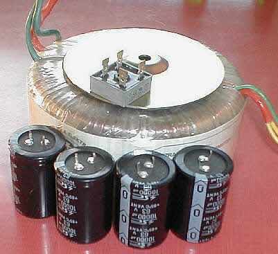
    I will be running everything in a dual mono type way with a trannie per every module with dual bridges and a 10000uF Elna Cerafine cap for filtering. Aside from this, what will need to be added to make a great supply? I have seen many different schematics but just don't know which to believe.

    Any help please.

    Thanks

    wasser
  • JonMarsh
    Mad Max Moderator
    • Aug 2000
    • 15298

    #2
    Everyone has their own hot button issues for offline linear power supplies...

    For moderately high power designs, I usually use 25-50 w aluminum case resistor for surge inrush limiting, with a relay bypass operated either by a simple timer circuit or the same circuit as the speaker relay control (which is usually also delayed, and of course, monitors for DC offset or very high power subsonics at the output).

    For very high power designs, I use a phase control SCR module to control charging of the output capacitors; this was done for a design which if the line could support it would draw up to 3 kW. On music, it usually ran fine with a 20A service- it was also configurable for 220V connection.

    I use dual bridge rectifiers with RC snubbers between each transformer winding and cap, with the common ground connected externally- this way, the transformer is only connected to the output supply when it's conducting current at the peak of the waveform- this minimizes amount of common mode noise which can be conducted through the transformer.

    I generally use filter capacitors selected for behavior in SMPS applications, which assures they have low ESL and low ESR, then usually bypass them with either metalized film or film and foil- in the range of 10uF or more.

    Actually, these days, I usually have about 1/3 of the supply capacitance in the amplifier module, so that the current loop in the output stage for high frequencies is very small; usually Nichicon 105C UHE caps for the main bypass, and SMD film caps to bypass at high frequencies. But these are analog stages. Goal is to minimize radiated high current energy which can effect low power gain circuits, and to provide a very low supply impedance characteristic for the amplifier stage. I usually have about 860uF per transistor in the output stage. The main AC bulk capacitance is +/-50,000uF per channel.

    I built a highly modified Dyna ST400 in the mid seventies, which foretold what Dynaco later offered in the ST416 with the outboard capacitor module, except my version had 100 uF of poly film caps.

    ~Jon
    the AudioWorx
    Natalie P
    M8ta
    Modula Neo DCC
    Modula MT XE
    Modula Xtreme
    Isiris
    Wavecor Ardent

    SMJ
    Minerva Monitor
    Calliope
    Ardent D

    In Development...
    Isiris Mk II updates- in final test stage!
    Obi-Wan
    Saint-Saƫns Symphonique/AKA SMJ-40
    Modula PWB
    Calliope CC Supreme
    Natalie P Ultra
    Natalie P Supreme
    Janus BP1 Sub


    Resistance is not futile, it is Volts divided by Amperes...
    Just ask Mr. Ohm....

    Comment

    • goskers
      Senior Member
      • Jun 2004
      • 106

      #3
      Whoa Jon,

      That was a lot to swallow for someone who knows very little about what you just said. I surely appreciate the time and words though.

      The RC snubber circuit before the trannie, what is it's purpose?

      I believe the UCD modules that I am using has HF, RC circuits onboard.

      Does anyone know anything about bypassing bridges? I have heard between 10nf and 100nf per rail and bridge.

      Thanks,

      wasser

      Comment

      • Meat_PoPs
        Junior Member
        • Nov 2004
        • 7

        #4
        I'd be very interested in hearing about / seeing schematics for your design when your done. I've dabbled in some amplifier design, but never made anything serious. A couple homebrew pwm 5watters but that's about it. Dreams of making it bigger were never realized due to limited sound quality, and limited knowledge about the finer points of high power powersupply/mosfet output designs.

        Comment

        • fishspeak
          Junior Member
          • Jul 2005
          • 1

          #5
          John,
          I know this is an old message but I just bought a Dynaco ST400 and I have a question. When I turn it on the light between the fuse holders on the front lights up but after about 3 - 4 seconds it goes off with a sound that sounds like a breaker tripping. The pilot light stays on and the amp seems to work. Is this anything to be concerned about.
          PS: I used your crossover for the RS180/ 27tdfc and enjoyed it very much. thanks for sharing.

          Howard Stever
          New Member

          Comment

          • thylantyr
            Senior Member
            • Nov 2004
            • 127

            #6
            I have seen many different schematics but just don't know which to believe.

            Power supplies are easy, they are essentially all the same,
            some add more tobasco sauce for spice but the basic design works well.


            I have a silly soft start circuit that someone requested.

            They wanted something funny where the user toggles
            the master switch to 'ON', then you press and hold a
            momemtary switch to start the 'amplifier' like a
            car ... :rofl:

            All you need is a sound module and small speaker
            to make the starter cranking sound

            When the master switch toggles off, it inserts the bleeder
            resistor across the caps to discharge and when it's on,
            the bleeder is removed, this is to allow very low impedance
            bleeder resistors to be used for a moment to discharge the
            cap bank fast, but not allowing the resistor to be in circuit
            while the amp is on, otherwise it an extra load you don't
            need to taxi the PS.

            Comment

            • cjd
              Ultra Senior Member
              • Dec 2004
              • 5570

              #7
              Heh.

              being the boring chip-amp guy I am (hey, I can actually put together circuits with these OK?) power supply gets a LOT of discussion. I absolutely believe (based on experiments) that it is the weak link for most designs that exist out there. But some of the existing "improvements" are just, well - bizarre. Multiple RC snubber circuits and lots of bypass caps.

              I'll probably get back into this stuff again more as the garden dies off and weather cools down.

              whee.

              But, Jon: You mostly lost me completely. :P But, surprisingly, only mostly, and that's a sign of progress!

              C
              diVine Sound - my DIY speaker designs at diVine Audio

              Comment

              • thylantyr
                Senior Member
                • Nov 2004
                • 127

                #8
                There are measured reasons why power supplies get alot
                of attention but how many of them translate into audibility? :lol:

                If you think about it, take a chip amp with a few parts.
                The design is so bare that there is really nothing to mod.
                Since there is little option to mod there, hey lets look at
                exotic power supply mods because we can :rofl:

                There are a few issues here. First, the person who created
                this thread wants to build a power supply for an amplifier
                but is confused because it's easy to get drowned in the
                hysteria. Second, to ease the pain I mentioned that power
                supplies are easy, which they are. One doesn't need a fancy
                power supply design to get the circuit up and running and
                enjoying the music. Third, this is DIY, not DUI of
                electronics :lol: , so get your basic circuit up and running,
                listen, enjoy and then try some esoteric ideas later to see
                if there is audible improvement.

                If you read DIYaudio.com or AA for tips then prepare to
                see fog.

                Comment

                • cjd
                  Ultra Senior Member
                  • Dec 2004
                  • 5570

                  #9
                  Originally posted by thylantyr
                  If you read DIYaudio.com or AA for tips then prepare to
                  see fog.
                  You don't say?!

                  Seriously, you're right. It can get crazy. I'm using a pretty bare bones power supply at the moment, and am generally happy with it.

                  You need: Transformer, rectifier bridge, cap(s). That's IT. And you don't really need much by way of capacitance for a bare bones circuit. Anything else is gravy. Granted, this circuit may not perform particularly well with a dynamic load, but that's a different issue (though with a big enough transformer, it may do just fine).

                  Now, if the transformer is big enough, you probably do need a soft-start circuit. That's a separate thing. A 20A circuit can probably handle the inrush of up to a 500VA trafo without *too* much trouble (that probably depends some on what you have for capacitance), though by that point I would certainly be considering some kind of soft-start setup.

                  C
                  diVine Sound - my DIY speaker designs at diVine Audio

                  Comment

                  • thylantyr
                    Senior Member
                    • Nov 2004
                    • 127

                    #10
                    In ancient times I paralleled four 500VA
                    transformers/rectifiers sharing the common cap bank
                    to get 2kva... because for that DIY project a 2kva custom
                    wound tranny was $800 and the 500VA off the shelf
                    ones were $45 each. I cheated, it worked and there was
                    no inrush protection. I think the capacitor bank was 200,000 uF total. Everything I bought was surplus.

                    You can get some really good cap deals from meci.com
                    or other sources and you can build a big bank for cheap.

                    Example, 4700uF cap, 50V - $4.26

                    The analphile would rather have the Black Gate
                    capacitor instead. Hey, that's cool by me. I just have
                    issues paying $99.95 each.


                    4700uF per rail! and that isn't alot of capacitance for
                    a very high end amplifier. Lets say you want 47,000uF
                    per rail.

                    Meci.com cost. 20 caps x $4.26 = $85

                    Black Gate cost. 20 caps x $99.95 = $1999.00

                    :rofl:

                    Bypass the cheap cap with the smaller cap like everyone
                    else does and pocket the $1900 savings and use it
                    elsewhere in the design that gives you more bang for buck :T

                    Plan B, Black Gate, is to use 8 - 10, 10,000 uF caps at
                    $170 each, so cost is about $1300 - $1700 vs. $1999 :lol:

                    Plan C, use the cheap cap bypass by smaller BG's.

                    Comment

                    Working...
                    Searching...Please wait.
                    An unexpected error was returned: 'Your submission could not be processed because you have logged in since the previous page was loaded.

                    Please push the back button and reload the previous window.'
                    An unexpected error was returned: 'Your submission could not be processed because the token has expired.

                    Please push the back button and reload the previous window.'
                    An internal error has occurred and the module cannot be displayed.
                    There are no results that meet this criteria.
                    Search Result for "|||"