-
You know, I keep thinking that I should purchase additional plunge bases for some of my routers. That way I can leave the various Jasper jigs on them and not need to worry about re-centering them every time. -
Work has started on the outer front panels for the LF modules...
Slow work takes time...
BTW, the Bosch RA1617EVS has sort of become the "official" project router, as there are now three on hand setup individually for specific kinds of tasks...Leave a comment:
-
I've been debating that issue with myself- I literally plan to clamp it up as you see above, except the right side panel not glued, nor the center baffle, with drivers loaded and check the impedance curve.
The other thing is that I can put an aperiodic damping baffle across the top of the center brace (good ole Denim insulation) and this would likely kill any vertical column resonance, being in what would be a high velocity low pressure area. The entire LF module will be lined in that material anyway.
I don't really expect it to occur in this design, though- the aspect ratio of width to height would encourage it, but the front to back aspect ratio is much more "normal", being about 2:1.
The diagnostic aid is that the RSS210HF's have such a clean impedance curve, anything unusual that shows up is due to effects like standing wave resonance.
Note- the FR30's are open top to bottom in a large area.Leave a comment:
-
Question: I believe in the past you have expressed concern about cabinet resonances. Since this is a fairly tall bass cabinet (40 inches, was it? I don't recall if that figure was internal or external) that would be somewhere around 330-340Hz. I see you have one brace extending the full depth of the cabinet, but with holes in it. Is this superior to using a solid brace instead, effectively creating two smaller cabinets with a resonance closer to the 700Hz range? Or is 300+Hz far enough above the working frequency of the bass cabinets it's not a concern?
Just trying to plan for my own project, which would be notably taller than this with a resonance of around 200Hz if I don't split the cabinet into sub compartments.Leave a comment:
-
Some detail development on bracing and internal design construction.
Leave a comment:
-
Slow work takes time, but get's done carefully- after two hours of cutting I can still touch the 3/4" router bit used for these initial slots- it's pretty warm, but nothing close to it's temperature limits. And every step on the router depth guide was used. Working with maple is quite different from Baltic Ply or cabinet grade MDF.
These are the inner front panels...
Next will be through cuts and clean up with a flush trim bit, then the backside bevels.
Slow work takes time...
Leave a comment:
-
The 1/2" solid carbide bits are for template cutting, cutting out the pattern for the front panel of the midrange-treble pattern, using a 3/8" thick phenolic template which I made (actually, there are two, one for the TPL075 cut out on the 1/4" panel before it's bonded to the main front panel, and then one for the primary rear cutouts for the tweeter and midrange section. These need to be deep, and will be followed up with a long 1/2" follower bit with the template on the other side of the panel, to get to the final dimension.Leave a comment:
-
Why use a 1/2" bit Jon? Are these cuts just for the countersink?Leave a comment:
-
And the LF module 2nd outer front was laminated up this morning.
Lately (the last 2-3 years) it seems like I've been migrating to more and more Bosch tools- in this project, I'm using two Bosch routers with the plunge base, (you can buy them with both fixed and plunge, or just one of the two - I converted my fixed base Bosch to dual mode recently), and they work quite well for this project for a couple of reasons.
One, Bosch offers an adapter that allows fitting template followers, and offers a selection of those in a kit, plus some individually, at different popular cutting diameter sizes.
Here, I have one router setup with the template adapter for doing 1/2" up cut work with a solid carbide router with a 1-1/2" cutting length. Here it is retracted...
And here extended.
I use these with my homemade templates constructed from phenolic tooling sheet.
The main task I worked on today besides shopping and lawn care was starting the cuts for the through holes on the inner front panels...
Here, a key useful feature of the Bosch router is the stepped plunge height fixture, with small steps between adjacent settings. This is key for working with a hardwood like the maple ply these panels are being fabricated from, as it's necessary to take small depth of cut on multiple passes.
Frankly, routing through materials like this maple ply probably takes at least 4x longer than common construction materials like cabinet grade MDF.
Here, I've got the starting point for two holes finished...
And one more...
Slow work takes time...
Leave a comment:
-
Step by step... inch by inch... slowly I build...
Some days the closest I can come to innovation is using some of the cut cabinet parts as tooling for assembling other parts...
Leave a comment:
-
Now, this next picture is just a "proof of ongoing work", AKA, WIP. No details, no comments, just showing that stuff is actually happening...
Of course, slow work takes time.
Leave a comment:
-
I'm in a very "experimental" stage of fabrication effort, and whether it will work or not in an open question. So I'm probably going to go dark on this for a while until I see if I come out the end of it with something that worked, or if I have to hit the reset button and try again. So far, the plan is working...
Leave a comment:
-
Continuing part prep for the MF-HF "module"
More watching the sausage get ground...
BTW, reminder, regarding these front panel "overlay" panels, and the purpose:- They serve two main purposes- taking care of the rebate cut out for the TPL075 tweeter
- Providing the additional front panel depth needed based on the updated crossover design and change in optimum Z-Axis offset of midrange to tweeter
- These are raw panels ~24" long, whereas the finished length of the MF-HF front panels is 19". There are reasons for this, including managing when and how the panels are trimmed to final length and at what stage of assembly. (AudioWorx manufacturing secretes, not to be confused with SMJ Audio manufacturing secrets, which are based on very different technology! No CNC at AudioWorx or DFAL!
- Initial stages of work and dimensions are dictated by the raw material dimensions to a degree- such as the 5" panel width of the maple boards, or the 5.5-6" width of solid veneer patterns.
Here are the two overlay panels after unclamping from veneering:
The veneer overlaps the edges, and has to be trimmed- on thin stock like this, I find the most straight forward way is a cutting knife with a fresh blade, and using the main stock as the edge guide:
Here you can see the first panel trimmed, looking at it flipped back over from the veneer side. I used a piece of masonite packed with some of my veneer stock as a protection element for the base of the cutting stack.
The next step is the basic/rough sanding of the veneer to remove the veneer tape and any leaked glue, if present. For this occasion, it seemed worthwhile to breakout the Festool orbital sander that I bought years ago at a special introductory discount and haven't yet used, saving it for a special project.
If this isn't special, I don't know what is...
Once both panels are sanded, the next step will be routing the TPL075 rebate using a template and template follower in my Bosch plunge router (nope, no CNC here!)
Leave a comment:
-
Once the veneer is completed, I may take all these posts and create an article on htguide for this. Great knowledge to share on this!Leave a comment:
-
Well, the fun never ends here, and neither does the work to be done!
I am making progress with my possibly questionable decision to veneer the 1/4" maple overlay panels, to get a consistent appearance and avoid cosmetic issues from some variations in these panels. Geez, the things I'll do for a good photo for the finished project!
Today's morning dalliance was prepping the veneer pieces, mixing up the West System epoxy I like to use for veneering (a bad habit I picked up doing the Wavecor Ardents and haven't been able to kick since- in fact, this last trip I brought back mixing cups from the original batch I bought FOR the Wavecor Ardents!).
Nothing at all complicated here, especially if you're familiar with setting up the West 105 resin and 205 hardener combo in their metal cans and supplied pump dispenser- it's easy enough for even me to use without issues!
I'm a little OCD about the veneer prep, even once it's dried- a trick that I've found works well is to use the nice easy release blue masking tape initially on the backside, to pull things together. with your fingers and apply the masking tape BEFORE using the veneer tape on the front side.
Looks sorta like this:
Flip it over...
Then you're ready to apply the veneer tape- when the cross pieces dry, they shrink, and that also helps pull things together at the seam.
Now, this is the point where having multiple irons in the fire can help- the underside support piece (bamboo here) is one of the cut sides for the Natalie P Ultra. Just the right size for supporting the work piece.
For assembly, I put down a piece of parchment paper, then the piece being veneered, and apply the epoxy to that with a flat spreader. A little goes a long way- about one squirt on the dispenser pumps for the 105 resin and 205 hardener.
Then, AFTER removing the masking tape from the back side of the veneer "assembly", position the veneer, then another piece of parchment paper, then another 1" bamboo side as the primary clamping plate.
Then additional cut pieces of the 1-1/4" maple ply for this project for the upper modules are stacked up to get clamping weight...
Both front panel overlay pieces are now veneered and clamped.
Of course, I'm using my favorite SawStop job site saw as the work table. Nice and flat.
Is that cheating?
I have an old saying to cover these situations, one that a Danish guy at work and I used a lot...
"If you're not cheating, you're not trying hard enough!"
🤣
Leave a comment:
-
The edge glued maple board front overlay panels for the woofer cabinet have been unclamped and sanded, and as ET would say, "Everything is proceeding according to plan...."
Leave a comment:
-
Secret glue up process.
You probably don't want to do these things they way I am- remember, I am no woodworker. I get things done, but I don't worry about cost or effort involved.
Leave a comment:
-
Work is progressing reasonably well, interleaved with other design tasks, landscaping work, general maintenance, communication, etc!
The the basic fabrication for the 1/4" maple overlays for the MF-HF module 19" front panels have been fabricated from the narrower panels available from the usual sources... these are 24" long, before cross cutting.
Supplies of Birdseye maple veneer from the original Wavecor Ardent project were brought over from CA last weekend, and now I've been flattening and drying veneer section to use for the front panel of the MF-HF module...
Here is the flattening/drying stack setup:
Ripped panels for the MF-HF panel are used for straightening weights.
Here, just before setting up the 3rd drying pass (not using newsprint, but Scott "rag" paper towels from a box). Parchment paper is used to isolate each veneer and paper stack.
Leave a comment:
-
I may end up putting them in the theater. Plan B is to put them upstairs where the Calliope were migrated too. Then I would take the Calliope up to my parents house that way when I'm up there visiting I have something fantastic to listen to. My parents are still using some Kenwood loud speakers from the 1970's. Plan C would move the Ardent D's upstairs and use the SMJ-40's in the theater as I can now do 2.0 or 5.1 for movies, Calliope to my parents house. It requires manually moving the XLR from the Emotiva to the DAC, but small change to enjoy a rich 2.0 listening experience now.
My reason for wanting to build the SMJ-40 was after listening to Efalegalo Isiris build and loving how they sound I want something with even more low end the Ardent D's. The low end was MOST impressive on the Isiris and if you ever get a chance to hear them you must do that. What also really blew me away was how similar the voicing is between the Isiris and Ardent D. I found that pretty impressive.
Leave a comment:
-
Nice! I might have Steve Manning make me the baffles for mine...haven't decided yet what materials I'll use though. Was kind of thinking about keeping this as low cost as possible, so MDF all around except maybe Baltic Birch baffles. Might wrap in 1/4 hardboard again though...we'll see. You must be going for the higher end version with the other tweeter. Great idea on the messages, I did not think of that! Wonder if I can go back in to complete that...
Do you know where you'll use these? I don't really see them replacing your mains in your theater. I only ask because I have absolutely no idea what I'll do with mine, at least while I'm in this house!
JonMarsh, you have an email good sir!Leave a comment:
-
Thanks for saving me some money this weekend Danny! I made the plunge... I will have Steve Manning put me in the queue to cut the cabinets at a later date. At least I could save a little now though 🤔. I left a comment on the parts on why I ordered too.
Leave a comment:
-
Welcome to the RSS210HF-4 club! You're nipping at my heels for the number of RSS210HF-4 on hand- I "only" have 8 RSS265PR's on hand, but I have 8 of the Seas SL26R XM003, also. -
Keep in mind the net LF enclosure target volume is 110L. The weight target for either PR is 350g; this requires adding one 75 gram disk to the SL26R XM003, or two 75 gram disks on the RSS265PR (it comes with 5 disks, so you actually have to remove 3 before using the PR).
Though the PR parameters are not identical, they're not very far off, and this is a comparison of the Unibox calculated response for 2.83VRMS with either PR in 110L. Note, this is the new version of the SL26R, the XM003 suffix.
RSS265PR
SL26R XM003
If you would PM me your email address, I can send both Unibox files.
The SL26R has a longer linear throw and theoretically a more linear Cms. It's also shiny, and cost more, but I got a pretty good deal with the wholesale account I have with a European distributor, buying 8 at once.
Leave a comment:
-
I never toss any info on a project in progress- will get that to you later today when I have access to my Mac StudioLeave a comment:
-
I'm sure that most know by now, but if you are interested in this project now may be a good time to purchase the subs, mids, and tweeters (if you're using the GRS model) from Parts Express - 12% off through Memorial Day with code MEMDAY2023.
I bit the bullet - Full PE version of the SMJ-40 will be here in a week, as well as a few extra parts for the new NatP. I really hope I do something with the 20 10" Dayton PRs and 14 8" subs I have now...my wife probably hopes I do too.
That reminds me JonMarsh , do you still have Unibox models for the SMJ-40 using the Dayton RSS265-PR? I'm pretty sure you had modeled it before settling on the Seas. Mostly curious how much of a volume change is necessary, if at all. I can run it myself if you don't have that anymore.Leave a comment:
-
I get private messages now and then about precision and setup in wood cutting- basically, acknowledging that they know CNC is the way to go if possible, but so few folks can access. So, the question is, how close can one get, say, just a wires and sparks guy like me? And of course, this is quite relevant to this project, as the materials I've chosen to work with are quite expensive and the last thing you want is yield loss... so the choice of measurement and marking setup, as well as execution with specific tools is fairly important... for ripping, crosscutting, and other operations.
So, the question boils down to, how close?
This close... target is 24".
Leave a comment:
-
Slow work takes time....
OK, this is going to be the boring period of this topic, waiting for me to get things done...
I've made an in-feed table, I'd call it a real Frankenstein monster, but it's not nearly that scary...
Think combining a sit-stand desk for small computers...
With a SawStop ST36 extension table top....
The rib design on the underside of the extension table top is a perfect layout for gluing to the computer table... put the two together with some marine epoxy, and Voila!
It has a substantial range of height adjustment...
And has no trouble supporting reasonable weight, like this Optima car battery for my FJ Cruiser.
Of course, the proof is in the pudding, so I did a test feed ripping 4 maple panels yesterday with my SawStop, and they all came out dead nuts on the very skinny lines on my metal rule for 8.5"- I doubt they're off by even 1/64"
After doing a full cutting plan this morning, two more 563D panels were ordered today from Piano Showcase.
I'd say something cute like, "Progress is our most important product", but Steve is not AT ALL happy with GE these days, so they are on our official "banned from the ranch" list.
Attached FilesLeave a comment:
-
-
Hey, I did my part to contribute to derailing!Though he lately came out with very different designs and constant claims the latest being the best yet... so no one knows what he really thinks...
I shall stop derailing now.
Last comment is that I think the 8 + 10 idea could work, but could be better implemented with different drivers and changes to the design.
Leave a comment:
-
But as a side note, Troels stood firm by his 8"+10" approach, and used it a few times in subsequent designs:
And even 10"+12", with same principle:
http://www.troelsgravesen.dk/ATS4-HE.htm
Though he lately came out with very different designs and constant claims the latest being the best yet... so no one knows what he really thinks...
I shall stop derailing now.Last edited by theSven; 19 May 2023, 10:45 Friday. Reason: Added images of these speakers in the event they are retired and the links breakLeave a comment:
-
Yes, 2x18WU/8741T00 in parallel (~700euro/side) for <400hz range seems rather opulent for most, especially with so many excellent and cheaper 8" woofers availablebut the price does tend to scare folks offLeave a comment:
-
Good examples, hitting 3 ohms in the upper bass area- I'm presuming these are all in parallel, right?
Those Illumintors are nice drivers, I've experimented with them, I think I have a pair of the 18WU/8747 aluminum version somewhere in storage, but the price does tend to scare folks off. And the paper one has a wicked high breakup mode, plus an edge resonance issue at about 1100 Hz. The Aluminum version has an even screwier top end, but it doesn't seem to have the edge resonance of the paper version. I was really interested in these because it's an exceptional underhung design and the motor should be very linear even with a fair amount of excursion, though the surround seems a bit narrow for 9 mm Xmax. That will impact Cms linearity with travel- that was one of the drawbacks of the Anarchy long throw mid woofers.
Leave a comment:
-
One other thing I notice is the overall voicing of the design-a considerable down tilt.
Between 60-70 Hz and 15kHz there is an overall down tilt in the modeled system response of about 5 dB. Much of this occurs between 60Hz and 1kHz. The midrange driver measured on axis appears to have a baffle diffraction issue around 1100 Hz or so, with a dip in the curve of about 2.5 dB.
An interesting thing is that the crossover function on the 26W driver is a bit like a bass boost function, not exactly like a 0.5 driver function, because it's tuned lower. The mid is rolling off between 700Hz and about 250Hz as a function of baffle step mainly... the high pass filter doesn't seem to much kick in until below 250Hz, and all three drivers seem to be contributing to output 150 Hz area- there isn't enough from the 26W. It would be fun to model this in VituixCAD if one knew the values, but you can only find out by buying the kit.
Leave a comment:
-
-
To paraphrase the old saying, "follow the physics".
The basic "speed" of step response is a function of the extension of the frequency response. But, considering the crossover points for the woofers, to achieve clean response on the upper end simply means ones needs to be able to hit the target response of the filter function that sums to the correct system response. Let's keep in mind that woofers are bandpass elements- and the "filter" alignments of the highpass (low frequency roll off in the mind of a speaker builder) have a lot of impact on energy storage and settling time compared with the upper range response, though as we've seen with so called Subwoofer drivers, they often have specific frequency response and distortion issues.
Both driver measurements by Troels are showing a dip in the response at 300Hz, which could be a function of the enclosure baffle shape and the effective baffle step behavior. Based on manufacturer data, it's not intrinsic to either driver.
22W/8534G00
26W/8534G00
Both have "speed" or upper transient response well in excess of requirements for their intended frequency range, and a review of the specifications shows the motors are essentially identical as regards T/S parameters, which are the building blocks for the low frequency high pass element of the band pass response. The 10" driver has an aluminum cone with higher SD and MMs, but the BL force factor has been tuned so that the effective Wes and Qts and Xmax are nearly identical.
The closed box factory recommendation for the 22W is 48L, giving an F3 of 52Hz. I don't get that using the DS parameters; in 48L, I'm seeing an Fb of 49Hz, but an F3 of 61Hz, because it's a bit over damped- it's not a B2 alignment, with a Qtc of 0.707, but a with a Q of 0.581. For a Butterworth 2 alignment, with a Qtc of 0.707, it's looking more like 24L. For a true critically damped alignment, a Qtc of 0.5, it requires about 95 dB, which also is a monkey coffin! Note, with either one, the settling time to a few percent is about 12ms.
The closed box factory recommendation for the 26W is 82L, giving an F3 of 39Hz.
The factory recommendation for vented for the 22W is 99L, with an Fb of 30Hz. This actually gives a response peak at about 36Hz, and a very sharp cut off, with a 0.36 dB dip in the range 50-70Hz. The F3 is 27 Hz. The settling time to a few percent is about 45-50msec, compared with 12ms sealed. This is a function of the corner Q with this driver's T/S parameters, the size of the enclosure, and the tuning.
Alternatively, a vented alignment I would suggest, with an enclosure volume 60L, and an Fb of 30Hz still, an F3 of 34 Hz is obtained with no peaking or local minima in the response. The driver still maintains loading from the vent down to 30Hz, but the output level down low is reduced, relatively wise considering the Xmax. Note, curiously, this is the size of the enclosure volume used by Troels for the 26W.
The vented box recommendation for the 26W is 173L, giving an F3 of 22Hz. Now, that's what I call a monkey coffin, no, actually a gorilla coffin! And it will have a very sharp corner and high Q and more ringing in the LF step response. Not recommended.
When I get back from travel I'll model the 26W, or I leave that as a homework assignment for anyone interested!
Last edited by theSven; 19 May 2023, 10:36 Friday. Reason: Update text size to be consistent for those with less than good eyes :-)Leave a comment:
-
Now, you KNOW I'm going to come back with some comments on that-
🤣
"My thinking here is primarily to improve the 100-200 Hz range by a dedicated bass driver in an aperiodic or closed cabinet with a smooth roll-off towards lower frequencies delivering a fast and dry bass and then having the 10C77 dealing with the rough part of pumping low-end bass"
So, what's implied here is using the sealed box with a small volume to provide a low frequency roll off for the 8" woofer, then match that with a crossover on the 10" woofer to provide a complementary response curve to the upper woofer...
This is the calculated response profile for the 22W8534 in 16L- this gives the high pass function.
Now, looking at the LSPCAD plotted transfer functions, you can see for Net 4 (the 26W/8534G00) that crossover SEEMS to be at around 100Hz, however, note that the upper woofer response calculated from his measured data (not shown) and the network for Net 3 indicates output pretty flat down to. about 60Hz, and this may be partially due to interaction between the L3011 and the Fb impedance peak. Now, I'm curious about the actual tuning of the 26W/8534G00 with it's dual ports, because if you look closely at the calculated LSPCAD response, it seems to be dropping rapidly below 60Hz, and he doesn't show data below 50Hz, which would normally be mini-monitor territory. But I'm pressed for time to get ready for a 650mile drive tomorrow, so I'm not doing any more Unibox analysis today.
This isn't surprising given the measured response from the two woofers:
22W
26W
Now, for the life of me, I don't see how the 26W is handling the low bass, and the 22W is handling the upper bass, based on these measurements, and the LSPCAD calculation of the total system response from Troels shown above, since their contributions at 50-60Hz are nearly equal, and both drop like a rock below that.
Now, this statement from Troels I'm in full agreement with:
What cannot be seen is what kind of bass performance we get in a given room. Bass performance is highly dependent on in-room placement of your speaker and the same speaker can be boomy in one place and lean in another. Actual SPL level at 1 meter distance and 2.8V input is useful for en estimate of system sensitivity and combined with the impedance profile may give an idea of how powerful an amplifier is needed to drive the speaker to adequate levels.
What measurements do not tell is the very sound of the speaker unless displaying serious linear distortion. The level of transparency, the ability to resolve micro-details, the "speed" of the bass, etc., cannot be derived from these data. Distortion measurements rarely tell much unless seriously bad, and most modern drivers display low distortion within their specified operating range.
This is why boundary analysis and setup methods such as the Cardas method, (using mathematical geometry) or the Wilson Audio method (using reciprocal response evaluated by ear or instrumentation) aren't just useful, they are "musts" in my opinion, and when I've persuaded other HTG members to try them out, they wind up in agreement about this.
This statement below, though, is partially problematic for me, as it implies that it's just not possible to ascertain any of this from measurements...
I agree that to ascertain it from HIS measurements may be quite difficult... but there are good reasons why more intensive measurements are quite useful, and quite useful for making evaluations and selection BEFORE you get to the listening stage... one can well characterize the acoustic behavior of those different cone materials, as well as that of different surround and suspension designs.Many people put way too much into these graphs and my comments here are only meant as warning against over-interpretation. There are more to good sound than what can be extracted from a few graphs. Every graph needs interpretation in terms of what it means sonically and how it impacts our choice of mating drivers, cabinet and crossover design.
What measurements certainly do not tell is the sonic signature of the drivers, because cones made from polyprop, alu, Kevlar, paper, glass fiber, carbon fiber, magnesium, ceramics or even diamonds all have their way of colouring the sound.
Just ask firms like PuriFi and BlieSMa for example. And ask me why I bought an Audio Precision APx555.
I don't think I've ever seen Troels do a distortion measurement, even just a simple swept sine evaluation, much less a multi-tone, or to examine sine bursts near potentially problematic areas like that edge resonance I suspected for the 26W.
Of course, now, I realize I don't make part or most of my living doing this like Troels does, and I've only been doing this since the late 70's, so he may have a leg up in experience. And I don't have an engineering degree, my formal education is in psychology. And I have a bad habit of looking closely at details and pointing out stuff others may not have wanted pointed out- a number of PhD's at my former employer have had to put up with that from time to time.
And I am a moderator, and should be more diplomatic, and also shouldn't allow a thread to go this far off topic.
But it's an interesting discussion, and I find it's rare that a thorough discussion doesn't clarify some things at some point.
One last point- for a reflex system, the Q of the overall alignment has a big impact on the step transient response- Unibox is a good tool for studying that. The cleanest ported reflex or PR step response will be for something more like a QB3 alignment- oddly, I don't see this issue discussed very often. I just had some 1:1 online messaging about this regarding potential subwoofer configurations and what I would recommend to get something close to critically damped response with a long throw driver. It wasn't the sort of alignment you usually see, but then the same lessons apply to speakers in a conventional frequency range.
Now, last goofy comment, going back to your idea of series 4 ohm drivers, and keeping to the same volume limitation as this Troels design for the LF, using two RSS210HF-4 in series in 65L net sealed will give you an F3 of 39Hz, an Fb of 36Hz, and an F6 of 30Hz- with good room placement, using Cardas technique, they will measure flat at the listening position to 30Hz due to boundary reinforcement. You'll need some more volts, though, but the impedance will be much higher.
And the LF step response will be quite "awesome", settling in about 12 msec. Keep in mind a step excitation covers a wide frequency range, from essentially sub sonic on up.
For the Saint-Saëns system design with PR's, the PR's are down in output by over 20dB when you get to 50Hz, the actual woofer level is down only 2dB at 40Hz. System Fb is 23 Hz and F3 is 26Hz. So the response basically goes an octave lower than the 8" + 10" design.
And that brings us back to our design concept, with 4 of the RSS210HF, because the extra two drivers increases apparent sensitivity by 3dB for the impedance and another 3dB for the additional acoustic radiators. Puts in in reasonably competitive turf.
Now, I've gotta finish packing AND go through a sprinkler controller manual and trouble shoot some stuff!
Leave a comment:
-
His reasoning for separating them and using different enclosures "My thinking here is primarily to improve the 100-200 Hz range by a dedicated bass driver in an aperiodic or closed cabinet with a smooth roll-off towards lower frequencies delivering a fast and dry bass and then having the 10C77 dealing with the rough part of pumping low-end bass"
Presumably, a woofer that's tuned to go as low as possible cannot maintain the speed and transient to reproduce superior midbass, that's why the closed box 8"Leave a comment:
-
And that sounds like compensating for issues that a basically flat 10" woofer has as a single radiating point, (I.E., floor bounce) when any position he chooses for that one woofer is something of a compromise.
Troels has developed some nice systems, but he uses more "HiFi verbiage" than I am comfortable, describing the subjective result desired, but saying little about why it occurs. It would be illuminating to see measurements of each woofer separately- and talking about transient punch isn't really addressing the physics of the design, IMO. If his initial placement for the 10" woofer results in floor bounce causing comb filter effects in the upper portion of the response, (fairly likely) then adding a second driver placed higher from the floor will have a different floor boundary interaction and may fill in the null area from floor bounce. That's physics.
In a predecessor project to the Isiris and Ardent, I did exactly that, with a dual SS 10" woofer setup, and discovered things about how the response varied just depending on the height of the driver array off the floor. This was the Modula Xtreme, which has a fairly long topic thread that dates back to early 2010.
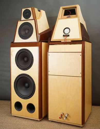
The original cabinet design concept, with a waveguide tweeter and Accuton C173-6-090 midrange, and dual SS 10" woofers:
This was measured and developed in a relatively small apartment living room. At time of this pic, I was checking near field response of the upper woofer. These were a special ScanSpeak part with high Qts designed for use in a smallish enclosure using series capacitor tuning element.
In room measured response- to get good LF info, a relatively long window is required, which picks up a lot of wall/boundary reflections. This was measured at 1M, which is not representative of the normal listening distance.
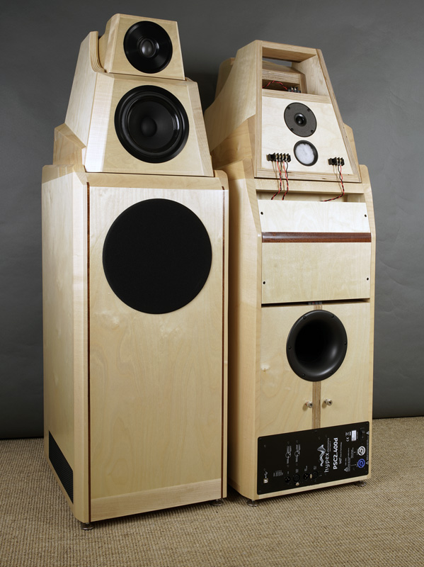
In consideration of my X1 SLAM Klone build, I "adjusted" the height of the system using another Dayton cabinet, empty, underneath.
Now, with the original stack setup, the measured response started getting pretty weird out at 2m or so in room. But with this setup, the first pass, keeping the original crossover, was fairly interesting at 2m...
The crossover was updated, with very satisfactory results sonically and measurement wise.
Now, these days we have tools that support diffraction and boundary effect modeling (VituixCAD) but in 2010, there wasn't anything like that around- just had to do it the hard way- in the real world.
Leave a comment:


Leave a comment: