
 Tweet
Tweet
So I've mentioned a couple of times about the SB65WBAC full range driver and how one of my projects for them is a bluetooth loudspeaker for a family member. Well I figured it'd be nice if I posted about them a little. A bit like Jon, although not by trade, I am more a sparks and wires guy than a making sawdust type. Don't get me wrong, I love building loudspeakers, but I always end up with a soldering iron in my hand far more often than I do the router!
So to get the ball rolling I'll start with a picture

These take heavily after CJD's Pecorinos with the idea of using a cast aluminium box and replacing the faceplate with something else. With this build used a powder coat black painted box from Hammond and replaced the front with some Yew that I scrounged cheaply from ebay.
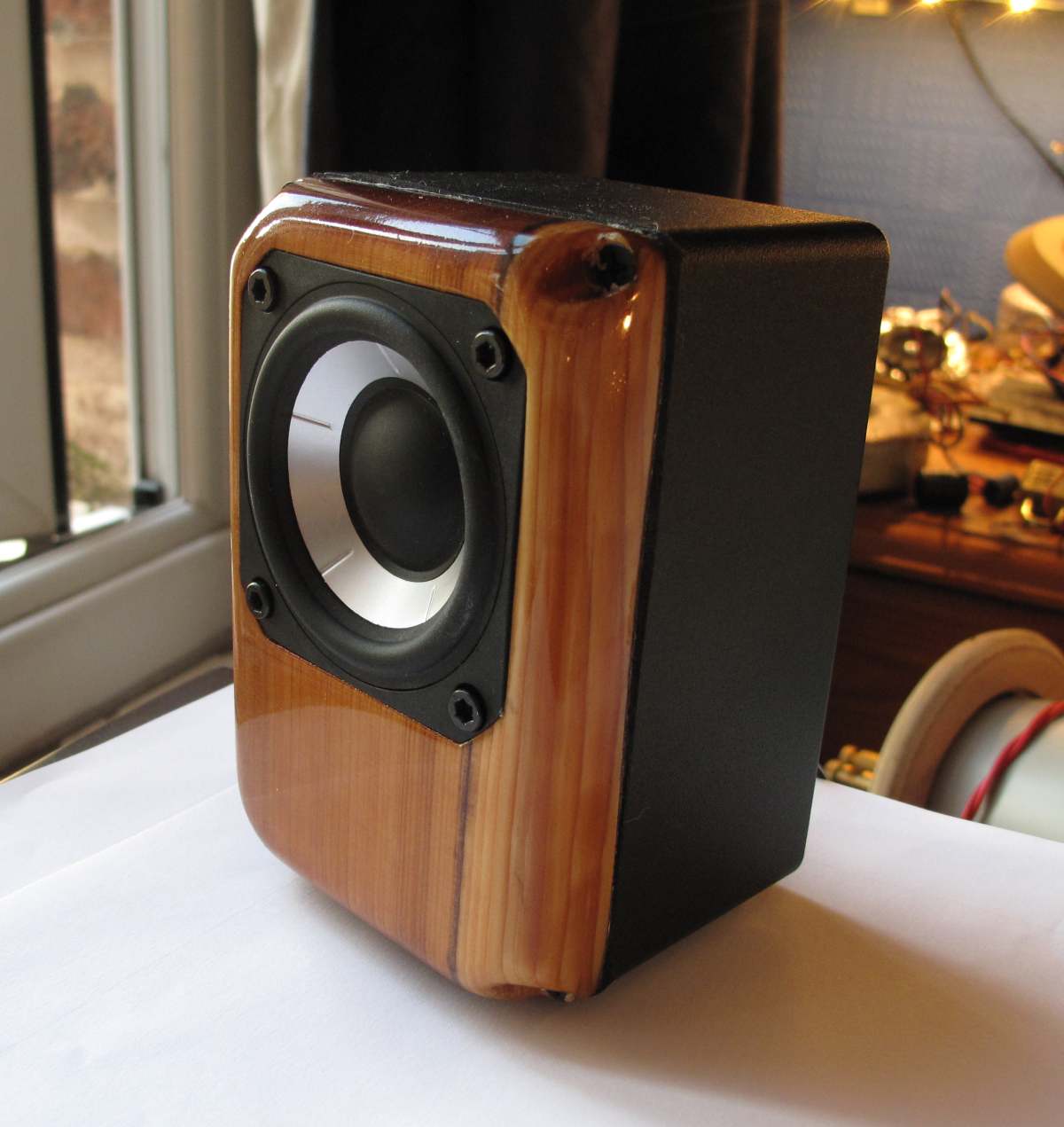
The driver rebates were cut using the Trend inlay kit that I mentioned in another thread.

Where I clamped the driver in a vice by the magnet, screwed a piece of MDF to the top of the driver via its screw holes (counter sinking in the screws) and ran a bottom bearing template cutter around the drivers basket in order to create an MDF version that I could use with the inlay kit. If you decide to do this you must remember to tape up the rear of the driver in order to stop any dust from getting into the delicate parts. The SB65 is particularly sensitive to this as it has a very well ventilated spider and has holes perforated within the voice coil former. The last thing you want to do is clog up the motor with MDF dust.
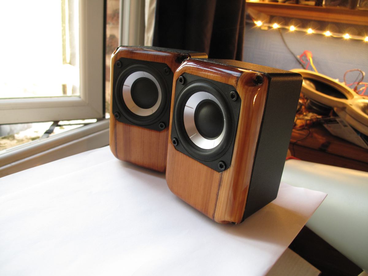
As you can see, the finish on these is relatively nice and was a bit of an experiment for me. I had read a lot about Tung oil in the past, but had never tried it, so I thought these would be perfect for giving it a go. Very quickly I realised that something wasn't quite right, in that the finish was not going to develop any kind of sheen or shine. Doing a quick bit of reading on the subject I realised that what most people use is polymerised Tung oil. This is a variant of Tung oil that already contains some oil based polyurethane and is specifically designed to give some shine to the appearance of the finished product. I had purchased Rustin's pure Tung oil, thinking this would be a decent idea, clearly this was not the right choice! To correct for this I tried putting some oil based poly into the Tung oil, along with some mineral spirits, but this didn't really work very well with the polyurethane only choosing the stick in a haphazard manner about the surface and coming off with the application of the next layer so nothing could really build up. Quite why this happened I am not sure so I tried removing the Tung oil from the mix and going with pure wipe on poly. This was a mix of about 30% oil based poly and 70% mineral spirits. This worked far better and after a few coats and some sanding I ended up with the finish you see here. What you can see here is just the top coat, I didn't have to sand and polish or anything, there are some particles of dust trapped on the surface, but otherwise it's completely even. Thumbs up for the wipe on poly. :T

As I mentioned before these do contain some electronics, although so far they just look like normal speakers. They are relatively simple in design and the buttons on the back of the left channel allow you to adjust the volume and turn the speakers on and off, as well as there being a connector for charging them, as they are battery operated. The two push button switches at the top, that control the volume, also have LED indicator rings around the button, like a vandal switch and display the bluetooth devices connection status and the charging status of the battery when they are plugged in.
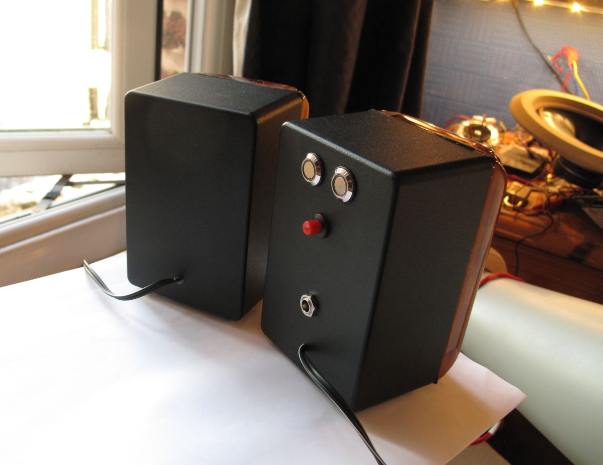
Even though these are wireless there is still a cable running from the left to the right channel for carrying the necessary signal.
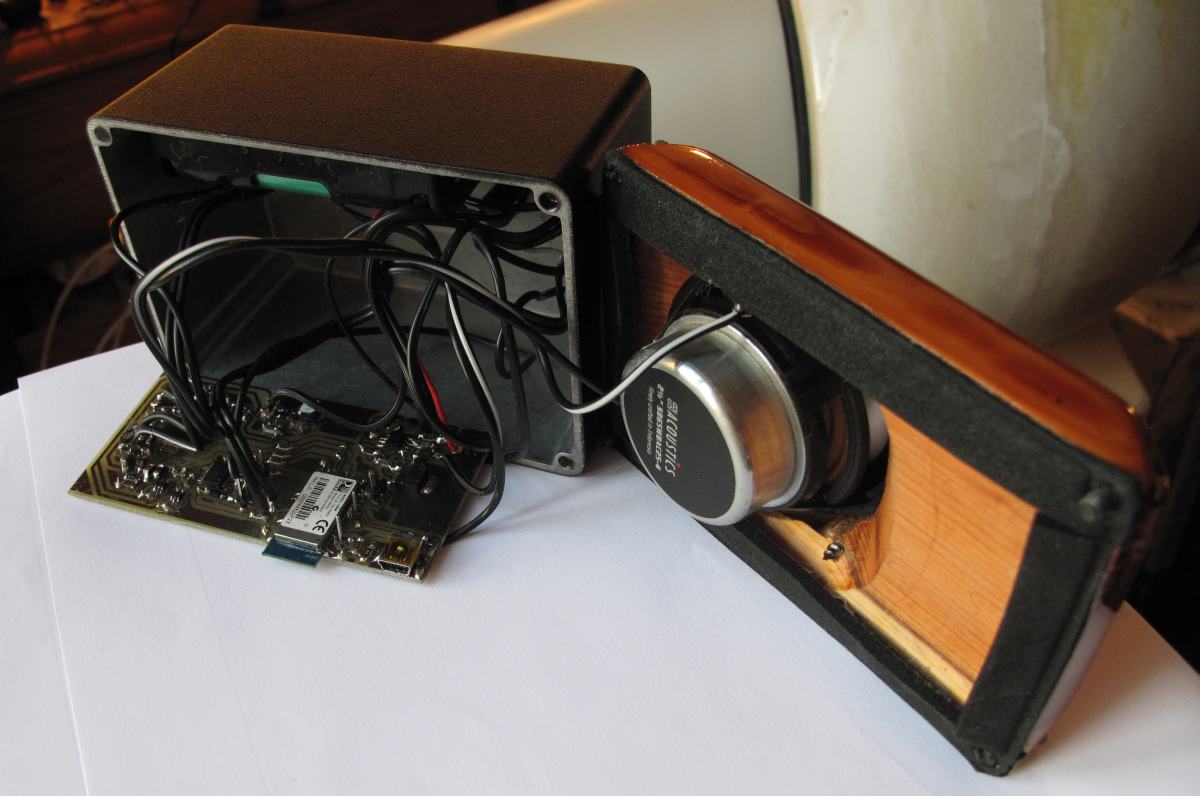
Here we have an internal shot of the left speaker with the stuffing removed. You can just about see the battery holder secured to the top of the box. These are two 3100mA hour Li-Ion batteries in series, providing enough voltage to operate the internal power amplifier. As you can see I placed a foam strip around the inside edge of the front baffle to ensure a decent seal between the two and to help prevent the aluminium box from ringing.
Now for the real sparks and wires bit :B
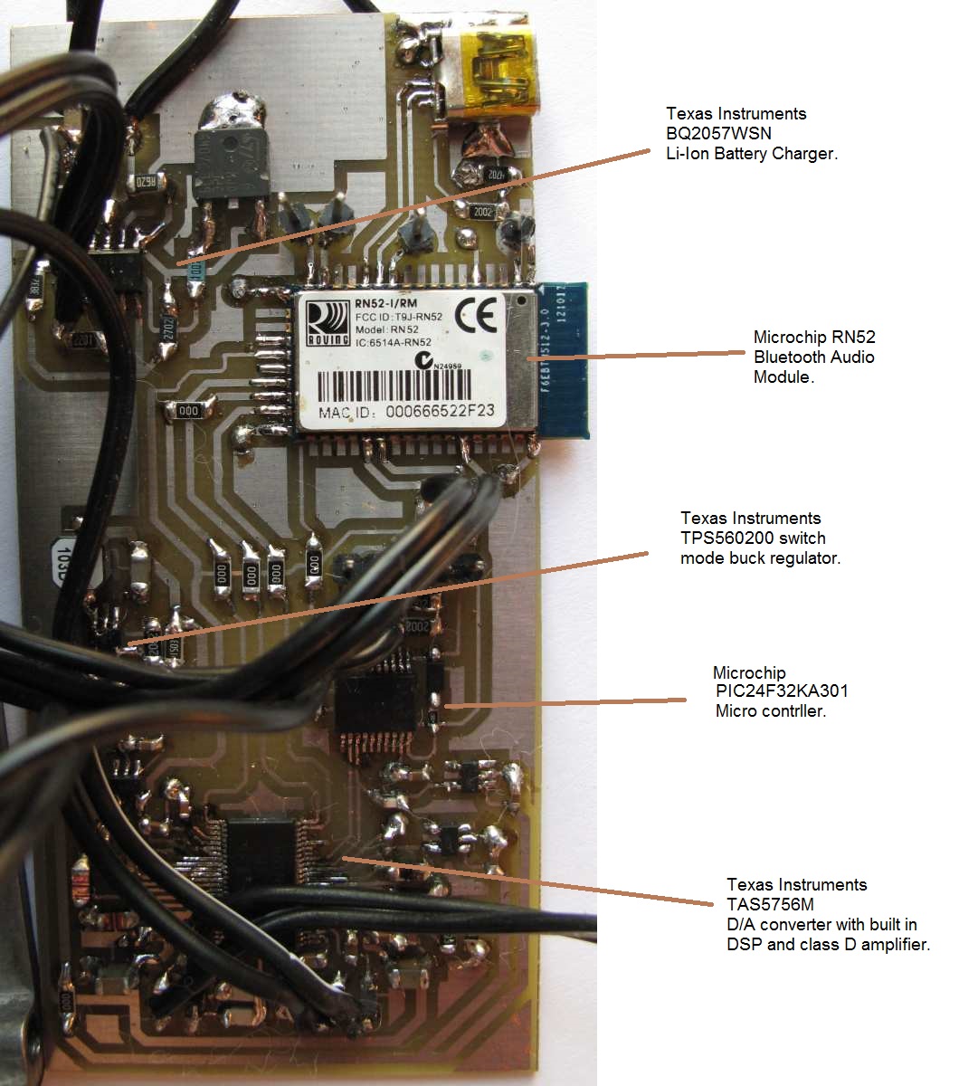
First off in the top left is the battery charging circuit. I did want to use a switched mode part for this, but those tended to be rather much more expensive and require significantly more parts to implement. The main advantage of switch mode battery charges is efficiency and flexibility, if you can run a linear charger, like I've used, from just the right voltage though a lot of those advantages become less important. This is mainly in dissipating the excess overhead of the power supply over the battery voltage, so if you keep the power supplies voltage just a smidgen over what's required, then far less is dissipated as heat. As it turns out commonly available supplies of 9volts work very well in this design.
The bit that does most of the hard work is the RN52 from Microchip. This is an audio sink device that will connect to any bluetooth source and output a variety of audio standards for interfacing with most types of audio companion devices. Here I have used it in I2S mode to send a digital signal directly into the audio power amplifier chip. To make this work you have to update the firmware on the RN52 to the latest version, v1.16 otherwise it will not work. The I2S functionality was incorrectly implemented prior to this update, so if you want to do this yourself, be warned. Also you need to have the ability to communicate with the RN52 via UART to program its various functions. This is easily achieved mind you using a USB to UART bridge, which you can buy cheaply from ebay along with a terminal emulator such as Putty. I have programmed these with a Raspberry Pi too, but that did have some issues.
Following on from the RN52 is the TAS5756M from TI. This, along with the SB65WBAC driver is a very new part, it has only been available for a couple of months and is critical to the design. TI's previous generation part needs far higher voltage rails to work it's output stage, whereas this part works down to much lower voltages meaning it will work from two series connected Li-Ion cells. I had been waiting a while for TI to finally release this part and as soon as they did I requested a couple of samples.
This is a rather complex IC for being so small and easy to implement, as it contains two channels of closed loop class D amplification, a digital to analogue converter and a DSP. All for the tiny cost of $2 when bought in substantial quantities. If you use short enough loudspeaker cables you can also get away with inductor-less operation for even greater power efficiency, something that is very much welcomed in a design such as this. As simple class D chip amps go it also has very decent technical performance.
To make all of this stuff work together is the microcontroller. This is one of microchips nanoWatt devices, again touted for it's high performance whilst drawing a tiny amount of current. The faster you run it the more power it draws. In this design I have it running as slowly as it can to still allow the I2C communications to work, but when doing so it draws about 200uAmps. This is my 'go-to' micro controller that I buy in quantity as it's relatively inexpensive whilst packing in a lot of useful peripheral functions.
I have mentioned power consumption a couple of times already, but the number one power management feature that helps to extend this projects battery life is the TPS560200 switched mode, buck regulator. If you aren't aware of how linear regulators, like the well known LM317 operate, then I'll give you a simple run down. Lets say you have a system that requires 5 volts to operate and is going to draw 1 amp whilst doing so. Lets also say that the power supply for the design outputs 10 volts. If you were to use a linear regulator to do this then 5 volts and 1 amp would be drawn from it and 10 volts and 1 amp would go into it. Here you have a difference of 5 volts between the input and the output at a current of one amp and this has to go somewhere. So what does the linear regulator do? It basically dumps the excess as heat. In this case you're using as much power in the actual system as you are losing in the regulator as heat. (You actually lose more than this as the regulator needs some power of its own to operate). In a lot of every day home appliances this isn't that much of a concern, linear regulators are cheap and very easy to implement. They are also very reliable and come with a plethora of protection features built in. All that happens is any excess heat usually contributes to the heating of your house, it's not the end of the world, but in portable applications it is very important. So is there a better way to do this? Sure there is, the switched mode, inductive buck regulator.
Inductive switched mode regulators work by exploiting the energy storage component of an inductor and work by turning a switch on and off very rapidly and alternately causing an inductor to charge and then discharge into a load. In doing so almost all of the energy entering the regulator circuit ends up discharging out of it via the inductor. The switch turns itself on when the voltage on the output of the regulator goes below a fixed point and then turns itself off when the voltage goes above a fixed point. When a voltage is regulated in this way, the traditional losses of a linear regulator are no longer present, nevertheless switch mode regulators have their own internal losses, but their efficiency is much, much higher.
In this design the average battery voltage is 7.4 volts. This feeds directly into the power amplifier section of the TAS5756M, but the DSP/DAC, the micro controller and the RN52 all ideally require 3.3. volts to operate correctly.
To put some of this into perspective the power amplifier, when idling, draws around 20mA whereas the rest of the circuitry, running from 3.3 volts, draws around 80mA. If linear regulators were used for the entire design (and I did try this in the preliminary design) then I'd be drawing around 100mA from the battery at all times, the vast majority of this being wasted as heat. In the preliminary design I measured 107mA average draw when the system was idling. I was hoping that I wasn't going to need to resort to using a switch mode converter, but alas 107mA didn't really give me the amount of battery life I was hoping for, so in came version two. In version two I used the buck regulator to first regulate down to 3.8 volts, before having three linear regulators cut this down to 3.3 volts, giving me three separate 3.3 volt rails. Like this the systems average draw is around 65mA. This almost doubles the battery life. Much better! In the first instance I would get around 28 hours of up time, whereas in the second instance I would get almost 48 hours.
Obviously none of this takes into consideration the extra current required to make sound. But if you're listening quietly to some classic music, or to the radio, then it makes a considerable difference.
Now back to the audio

The final part of this project shows the curve that is loaded into the DSP of the TAS5756M. This basically compensates for baffle step losses, applies a bit of gain around 700Hz, high pass limits the driver in order to protect it from bass it cannot cope with, corrects for the slightly high Q response of the small enclosure via a Linkwitz Transform and extends it a little by around half an octave.
How do they sound? Great ;x(
The SB65WBAC is a fantastic little driver and it's rising high frequency response is rather useful as it allows you to tailor the sound to your liking via the amount of toe in you use.
So to get the ball rolling I'll start with a picture
These take heavily after CJD's Pecorinos with the idea of using a cast aluminium box and replacing the faceplate with something else. With this build used a powder coat black painted box from Hammond and replaced the front with some Yew that I scrounged cheaply from ebay.
The driver rebates were cut using the Trend inlay kit that I mentioned in another thread.
Where I clamped the driver in a vice by the magnet, screwed a piece of MDF to the top of the driver via its screw holes (counter sinking in the screws) and ran a bottom bearing template cutter around the drivers basket in order to create an MDF version that I could use with the inlay kit. If you decide to do this you must remember to tape up the rear of the driver in order to stop any dust from getting into the delicate parts. The SB65 is particularly sensitive to this as it has a very well ventilated spider and has holes perforated within the voice coil former. The last thing you want to do is clog up the motor with MDF dust.
As you can see, the finish on these is relatively nice and was a bit of an experiment for me. I had read a lot about Tung oil in the past, but had never tried it, so I thought these would be perfect for giving it a go. Very quickly I realised that something wasn't quite right, in that the finish was not going to develop any kind of sheen or shine. Doing a quick bit of reading on the subject I realised that what most people use is polymerised Tung oil. This is a variant of Tung oil that already contains some oil based polyurethane and is specifically designed to give some shine to the appearance of the finished product. I had purchased Rustin's pure Tung oil, thinking this would be a decent idea, clearly this was not the right choice! To correct for this I tried putting some oil based poly into the Tung oil, along with some mineral spirits, but this didn't really work very well with the polyurethane only choosing the stick in a haphazard manner about the surface and coming off with the application of the next layer so nothing could really build up. Quite why this happened I am not sure so I tried removing the Tung oil from the mix and going with pure wipe on poly. This was a mix of about 30% oil based poly and 70% mineral spirits. This worked far better and after a few coats and some sanding I ended up with the finish you see here. What you can see here is just the top coat, I didn't have to sand and polish or anything, there are some particles of dust trapped on the surface, but otherwise it's completely even. Thumbs up for the wipe on poly. :T
As I mentioned before these do contain some electronics, although so far they just look like normal speakers. They are relatively simple in design and the buttons on the back of the left channel allow you to adjust the volume and turn the speakers on and off, as well as there being a connector for charging them, as they are battery operated. The two push button switches at the top, that control the volume, also have LED indicator rings around the button, like a vandal switch and display the bluetooth devices connection status and the charging status of the battery when they are plugged in.
Even though these are wireless there is still a cable running from the left to the right channel for carrying the necessary signal.
Here we have an internal shot of the left speaker with the stuffing removed. You can just about see the battery holder secured to the top of the box. These are two 3100mA hour Li-Ion batteries in series, providing enough voltage to operate the internal power amplifier. As you can see I placed a foam strip around the inside edge of the front baffle to ensure a decent seal between the two and to help prevent the aluminium box from ringing.
Now for the real sparks and wires bit :B
First off in the top left is the battery charging circuit. I did want to use a switched mode part for this, but those tended to be rather much more expensive and require significantly more parts to implement. The main advantage of switch mode battery charges is efficiency and flexibility, if you can run a linear charger, like I've used, from just the right voltage though a lot of those advantages become less important. This is mainly in dissipating the excess overhead of the power supply over the battery voltage, so if you keep the power supplies voltage just a smidgen over what's required, then far less is dissipated as heat. As it turns out commonly available supplies of 9volts work very well in this design.
The bit that does most of the hard work is the RN52 from Microchip. This is an audio sink device that will connect to any bluetooth source and output a variety of audio standards for interfacing with most types of audio companion devices. Here I have used it in I2S mode to send a digital signal directly into the audio power amplifier chip. To make this work you have to update the firmware on the RN52 to the latest version, v1.16 otherwise it will not work. The I2S functionality was incorrectly implemented prior to this update, so if you want to do this yourself, be warned. Also you need to have the ability to communicate with the RN52 via UART to program its various functions. This is easily achieved mind you using a USB to UART bridge, which you can buy cheaply from ebay along with a terminal emulator such as Putty. I have programmed these with a Raspberry Pi too, but that did have some issues.
Following on from the RN52 is the TAS5756M from TI. This, along with the SB65WBAC driver is a very new part, it has only been available for a couple of months and is critical to the design. TI's previous generation part needs far higher voltage rails to work it's output stage, whereas this part works down to much lower voltages meaning it will work from two series connected Li-Ion cells. I had been waiting a while for TI to finally release this part and as soon as they did I requested a couple of samples.
This is a rather complex IC for being so small and easy to implement, as it contains two channels of closed loop class D amplification, a digital to analogue converter and a DSP. All for the tiny cost of $2 when bought in substantial quantities. If you use short enough loudspeaker cables you can also get away with inductor-less operation for even greater power efficiency, something that is very much welcomed in a design such as this. As simple class D chip amps go it also has very decent technical performance.
To make all of this stuff work together is the microcontroller. This is one of microchips nanoWatt devices, again touted for it's high performance whilst drawing a tiny amount of current. The faster you run it the more power it draws. In this design I have it running as slowly as it can to still allow the I2C communications to work, but when doing so it draws about 200uAmps. This is my 'go-to' micro controller that I buy in quantity as it's relatively inexpensive whilst packing in a lot of useful peripheral functions.
I have mentioned power consumption a couple of times already, but the number one power management feature that helps to extend this projects battery life is the TPS560200 switched mode, buck regulator. If you aren't aware of how linear regulators, like the well known LM317 operate, then I'll give you a simple run down. Lets say you have a system that requires 5 volts to operate and is going to draw 1 amp whilst doing so. Lets also say that the power supply for the design outputs 10 volts. If you were to use a linear regulator to do this then 5 volts and 1 amp would be drawn from it and 10 volts and 1 amp would go into it. Here you have a difference of 5 volts between the input and the output at a current of one amp and this has to go somewhere. So what does the linear regulator do? It basically dumps the excess as heat. In this case you're using as much power in the actual system as you are losing in the regulator as heat. (You actually lose more than this as the regulator needs some power of its own to operate). In a lot of every day home appliances this isn't that much of a concern, linear regulators are cheap and very easy to implement. They are also very reliable and come with a plethora of protection features built in. All that happens is any excess heat usually contributes to the heating of your house, it's not the end of the world, but in portable applications it is very important. So is there a better way to do this? Sure there is, the switched mode, inductive buck regulator.
Inductive switched mode regulators work by exploiting the energy storage component of an inductor and work by turning a switch on and off very rapidly and alternately causing an inductor to charge and then discharge into a load. In doing so almost all of the energy entering the regulator circuit ends up discharging out of it via the inductor. The switch turns itself on when the voltage on the output of the regulator goes below a fixed point and then turns itself off when the voltage goes above a fixed point. When a voltage is regulated in this way, the traditional losses of a linear regulator are no longer present, nevertheless switch mode regulators have their own internal losses, but their efficiency is much, much higher.
In this design the average battery voltage is 7.4 volts. This feeds directly into the power amplifier section of the TAS5756M, but the DSP/DAC, the micro controller and the RN52 all ideally require 3.3. volts to operate correctly.
To put some of this into perspective the power amplifier, when idling, draws around 20mA whereas the rest of the circuitry, running from 3.3 volts, draws around 80mA. If linear regulators were used for the entire design (and I did try this in the preliminary design) then I'd be drawing around 100mA from the battery at all times, the vast majority of this being wasted as heat. In the preliminary design I measured 107mA average draw when the system was idling. I was hoping that I wasn't going to need to resort to using a switch mode converter, but alas 107mA didn't really give me the amount of battery life I was hoping for, so in came version two. In version two I used the buck regulator to first regulate down to 3.8 volts, before having three linear regulators cut this down to 3.3 volts, giving me three separate 3.3 volt rails. Like this the systems average draw is around 65mA. This almost doubles the battery life. Much better! In the first instance I would get around 28 hours of up time, whereas in the second instance I would get almost 48 hours.
Obviously none of this takes into consideration the extra current required to make sound. But if you're listening quietly to some classic music, or to the radio, then it makes a considerable difference.
Now back to the audio
The final part of this project shows the curve that is loaded into the DSP of the TAS5756M. This basically compensates for baffle step losses, applies a bit of gain around 700Hz, high pass limits the driver in order to protect it from bass it cannot cope with, corrects for the slightly high Q response of the small enclosure via a Linkwitz Transform and extends it a little by around half an octave.
How do they sound? Great ;x(
The SB65WBAC is a fantastic little driver and it's rising high frequency response is rather useful as it allows you to tailor the sound to your liking via the amount of toe in you use.

 unk:
unk:
Comment