An attempt to make a 3 way floorstander with DSP-based crossover

Collapse
X
 
  • Time
  • Show
Clear All
new posts
  • vineethkumar01
    Junior Member
    • Aug 2020
    • 11

    An attempt to make a 3 way floorstander with DSP-based crossover

    Hi All,

    I have been reading and learning from posts in this forum for quite some time now but have not interacted much due to my limited knowledge and the very high standards that I see in all speaker projects posted here. I have been very inspired by the projects here. Finally, I have gathered the courage to make a post here.

    I want to study and design a DSP-based 3 way speaker using VituixCAD for crossover design. I have selected the following drivers for this project (I have these drivers with me):
    1) Satori WO24P-8 for Woofer
    2) SB15CAC30-8 for midrange
    3) SB26CDC-C004 as the tweeter in a 4 inch elliptical waveguide by FM augerpro.

    I started with generating a crossover configuration based on traced SPLs of these drivers from their datasheets (Now I know that ideally, we should put the drivers in the intended cabinet and then take measurements and then design crossover based on it). The simulations that I have attached along with this post have these drivers placed on a baffle of width 32cm and height 105 cm (with 20mm edge rounding for easing diffraction-related anomalies. The woofer is assumed to be put in sealed box of size 55L, midrange also in a sealed enclosure of about 12 L). The tweeter was not put in a waveguide. With my limited knowledge, I designed a crossover for this system as shown in attached image. The VituixCAD six pack showing resultant system response details is also attached.

    However, as per the advice I received in other forums to move to a measurement based design and stop wasting time using traced SPLs, I have slowly built up a setup to take measurements using ESI U86XT audio interface and a Dayton EMM-6 measurement mic.
    As a first attempt, I have made a prototype of the top half of the intended baffle and started studying taking actual measurements using REW.

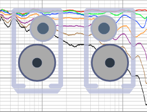
    Here are some pics of temporary baffle, measurements and resulting frequency response measurements, over 50 degree angle (0 to 50 degree or 10 to 60 degree, I lost one of the measurements, not sure which one).
    I made the baffle out of insulation foam material and carved the angular shapes/chamfers on the baffle out of it using pen knives. The dimensions are similar to the intended final widths and final look of the baffle (at least the top half of it). As of now, I am very happy with this preliminary attempt where I have been able to capture the horizontal off axis behavior of a waveguide to some extent.

    Now, I am having some confidence with more measurements and finalizing box shape for building it. Next step is to refine the measurement setup like pillows on the floor, making the transition from mic to PVC pipe seamless, better positioning of overall setup, etc etc... and bringing in VituixCAD into the workflow.

    Kindly guide me on any improvements that can be made on anything related to this project. Whether it is about the box size or shape or improvement in making measurements or any other aspect.

    Looking forward to learn more from your valuable opinions.

    (Didn't understand how to attach images with this post yet, hence making an attempt by hosting the images in google drive and sharing link here)


    Thanks
    Vineeth
    Last edited by vineethkumar01; 22 September 2021, 10:48 Wednesday.
  • xandresen
    Member
    • Feb 2015
    • 49

    #2
    While the "wisdom" on the forum is to take measurements on a baffle the size of the speaker's front panel, that does not work so well with a 3-way, IMHO.

    Also you are using a waveguide on the tweeter so tweeter diffraction only occurs below where the waveguide stops working. below 2KHz? Your diffraction is primarily from the midrange and woofer.

    My approach (with DSP) is to take gated driver measurements on a 5 foot diameter test baffle. This gives "infinite baffle" results down to around 300Hz, and to check with a near-field driver measurement below 300Hz to be sure response is fairly flat. Merge this "infinite" response with box model response as usual. Then I equalize each driver flat over its useful range using Linkwitz-Riley transforms and a modest amount of EQ, then use ideal Linkwitz-Riley crossover filters.

    My speakers use the woofer + midrange you chose, I modeled the baffle diffraction step and got a 1 to 2 dB peak around 800Hz, falling off down to 100Hz or so (cabinet width = 10 5/8", 27cm). In-room measurements to accurately determine shape and amplitude of the diffraction step over this range are not practical.

    I used baffle diffraction modeling software to determine the general shape of the rolloff for the midrange + woofer (while considering the 800Hz peak as a separate equalization step). Then matched that rolloff as best I could with a second order shelving filter that is applied to the audio input before other equalization or crossovers. (High-Shelf, Freq= 250Hz, Q = 0.5)

    Tradition says a baffle step of 4 to 5 dB is needed for a box speaker in a typical listening room. After listening to many recordings I chose 4 dB as my step amplitude. My classical music recordings vary +-2dB in their lower bass loudness so there's no exact answer! Of course with DSP you can change this amplitude in seconds.

    You can also create a seperate EQ to correct the lower bass level variations in recordings. I am using High-Shelf, Freq= 175Hz, Q = 0.5, gain normally set to 0 dB.

    Hope this info is of some help. Please understand I left out many details.
    Last edited by xandresen; 22 September 2021, 15:11 Wednesday. Reason: add cabinet width

    Comment

    • vineethkumar01
      Junior Member
      • Aug 2020
      • 11

      #3
      Thanks a lot for your reply.
      Your method gives me a new perspective on this design process. However, I have some general questions.
      1. Could you please explain/show a picture of the box shape that you chose for this particular speaker?
      2. What are the general principles applied in EQing the drivers to have a flat response?
      3. Is the 'infinite baffle' response that you measured using the test baffle used to isolate the driver response alone from the baffle diffraction related anomalies and then use EQ to flatten the driver frequency response while leaving out EQing the baffle diffraction-related anomalies?
      4. Is the nearfield response measurement (and trying to match it with box model response) done again to isolate the driver response and EQ it similar to above?
      5. From my limited understanding any EQ we apply in this kind of setup will affect the driver response to the on-axis response and to all off-axis responses. How do we achieve a balance between the ON-axis and OFF-axis responses while using EQ.
      6. At least for checking how the EQ + crossover filters change the radiation characteristics of the overall system (all drivers+box) in both horizontal and vertical planes, wouldn't we need to measure the complete ON+OFF axis responses?
      7. In summary, does this mean that we need to take two sets of measurements:
      a) ON and OFF axis measurements in an infinite baffle-like setup for isolating driver response anomalies and EQing it + designing crossover filters,
      b) ON and OFF axis measurements of the overall system to check for the overall radiation characteristics including power response and directivity

      Thanks
      Vineeth
      Last edited by vineethkumar01; 23 September 2021, 00:47 Thursday. Reason: for better formatting

      Comment

      • Juhazi
        Senior Member
        • May 2008
        • 239

        #4
        Vineeth, I think that you are making this too difficult! Remember, you are using multichannel dsp anyway! DSP units have graphical and easy to use software for manual settings. Making full dsp settings in some simulation SW and downloading that in dsp is awkward IMO, unless you are making a perfect clone of a ready-made project.

        So, you have made your choice of drivers already, and you have the responses from datasheets. No need to measure them in a test baffle by yourself.
        You can study baffle effect by simple simulations like The Edge or VituixCAD simulation module. This is to learn basics of what baffle dimensions/shape, driver diameter and it's positioning on the baffle, how they modify "ideal" response
        Also you can do a simple simulation of low bass response in the box volume and possible BR tuning you want

        Then if you want confirmation to your guesses, make a simple test baffle that has the dimensions and shape of final speaker, and do gated indoor measurements of midrange and tweeter only
        - first without any eq or gain levelling at say 0, 15, 30, 45 and 60 deg off-axis horizontally and vertically - study these and distortion, then think about off-axis behaviour to decide where xo should be
        - then manually and individually equalize mid and tweeter's on-axis responses to be flat at least one (preferably two) octaves beyond xo (no need to create dsp parameters by simulation program, because there will be differencies anyway)
        Then set gain levels to match between mid and tweeter
        Then set MT crossover slopes in dsp and take on-axis measurements. Study how xo works and set delay of the tweeter to get best possible summation and step response
        Then measure mid-tweeter system 0-90 (180) deg and evaluate off-axis behaviour ( it will neve be perfect!) and try different xo types and frequencies (trial and error)

        Then the difficult part is how to measure and eq the woofer in the box! Indoor measurement are very difficult and even frustrating... Outdoor ground plane measurement is best, mic on the ground at 2m distance
        First equalize the responese flat, then set gain level, then set WM crossover slopes and delays, and take measurements - make corrections

        All this will take several days!

        When the speaker gives nice response outdoors, carry it in your room and take listening spot measurements with 500ms gating or RTA. Then do general room-eq settings for the speaker system (not touching each driver's eq!)

        Enjoy!

        Digital crossovers are one of the key core strengths of the miniDSP range of products. In this app note, we'll provide an overview of digital crossovers and how they differ from passive crossovers and other types of active crossover. With a high degree of flexibility, user-friendly interfaces, and unbeatable value, miniDSP digital crossovers offer the perfect solution for both the DIYer and the loudspeaker/system professional.


        Share your videos with friends, family, and the world
        Last edited by Juhazi; 23 September 2021, 05:46 Thursday.
        My DIY speaker history: -74 Philips 3-way, -82 Hifi 85B, -07 Zaph L18, -08 Hifitalo AW-7, CSS125FR, -09 MarkK ER18DXT, -13 PPSL470Dayton, -13 AINOgradient, -18 Avalanche AS-1 dsp, -18 MR183w

        Comment

        • vineethkumar01
          Junior Member
          • Aug 2020
          • 11

          #5
          Originally posted by Juhazi
          Vineeth, I think that you are making this too difficult! Remember, you are using multichannel dsp anyway! DSP units have graphical and easy to use software for manual settings. Making full dsp settings in some simulation SW and downloading that in dsp is awkward IMO, unless you are making a perfect clone of a ready-made project.

          So, you have made your choice of drivers already, and you have the responses from datasheets. No need to measure them in a test baffle by yourself.
          You can study baffle effect by simple simulations like The Edge or VituixCAD simulation module. This is to learn basics of what baffle dimensions/shape, driver diameter and it's positioning on the baffle, how they modify "ideal" response
          Also you can do a simple simulation of low bass response in the box volume and possible BR tuning you want

          Then if you want confirmation to your guesses, make a simple test baffle that has the dimensions and shape of final speaker, and do gated indoor measurements of midrange and tweeter only
          - first without any eq or gain levelling at say 0, 15, 30, 45 and 60 deg off-axis horizontally and vertically - study these and think about off-axis behaviour to decide where xo should be
          - then manually and individually equalize mid and tweeter's on-axis responses to be flat at least one (preferably two) octaves beyond xo (no need to create dsp parameters by simulation program, because there will be differencies anyway)
          Then set gain levels to match between mid and tweeter
          Then set MT crossover slopes in dsp and take on-axis measurements. Study how xo works and set delay of the tweeter to get best possible summation and step response
          Then measure mid-tweeter system 0-90 (180) deg and evaluate off-axis behaviour ( it will neve be perfect!) and try different xo types and frequencies (trial and error)

          Then the difficult part is how to measure and eq the woofer in the box! Indoor measurement are very difficult and even frustrating... Outdoor ground plane measurement is best, mic on the ground at 2m distance
          First equalize the responese flat, then set gain level, then set WM crossover slopes and delays, and take measurements - make corrections

          All this will take several days!

          When the speaker gives nice response outdoors, carry it in your room and take listening spot measurements with 500ms gating or RTA. Then do general room-eq settings for the speaker system (not touching each driver's eq!)

          Enjoy!

          Digital crossovers are one of the key core strengths of the miniDSP range of products. In this app note, we'll provide an overview of digital crossovers and how they differ from passive crossovers and other types of active crossover. With a high degree of flexibility, user-friendly interfaces, and unbeatable value, miniDSP digital crossovers offer the perfect solution for both the DIYer and the loudspeaker/system professional.


          https://www.youtube.com/user/kimmosto/videos

          Thanks a lot for specifying the different steps in the design. I am finding the links you posted above very interesting and will definitely go through them.
          In fact I am already in the process of learning and using VituixCAD and have seen the videos multiple times already. :-)
          It is an incredible software.
          I used it to develop the preliminary crossover from traced SPLs and used its enclosure, baffle diffraction, and calculator tools to get the responses I attached with my first post.
          Since I wanted to study taking more real measurements in a prototype enclosure, as the first part I made some preliminary measurements of the waveguided tweeter in a test baffle and attached what I got in the first post.
          As the next step, I am planning to complete a quick prototype enclosure just for the mid & tweeter part and will explore some crossover design aspects using VituixCAD.
          Once, I am comfortable with it, I am planning to get help for building the full enclosure and thereafter follow the steps that you suggested for the woofer-mid crossover.
          Only difficulty for me is, in the concrete jungle that I live it is very hard to get outdoor measurements, even at night. I will try.

          Thanks
          Vineeth

          Comment

          • xandresen
            Member
            • Feb 2015
            • 49

            #6
            Originally posted by vineethkumar01
            Thanks a lot for your reply.
            Your method gives me a new perspective on this design process. However, I have some general questions.
            1. Could you please explain/show a picture of the box shape that you chose for this particular speaker?
            2. What are the general principles applied in EQing the drivers to have a flat response?
            3. Is the 'infinite baffle' response that you measured using the test baffle used to isolate the driver response alone from the baffle diffraction related anomalies and then use EQ to flatten the driver frequency response while leaving out EQing the baffle diffraction-related anomalies?
            4. Is the nearfield response measurement (and trying to match it with box model response) done again to isolate the driver response and EQ it similar to above?
            5. From my limited understanding any EQ we apply in this kind of setup will affect the driver response to the on-axis response and to all off-axis responses. How do we achieve a balance between the ON-axis and OFF-axis responses while using EQ.
            6. At least for checking how the EQ + crossover filters change the radiation characteristics of the overall system (all drivers+box) in both horizontal and vertical planes, wouldn't we need to measure the complete ON+OFF axis responses?
            7. In summary, does this mean that we need to take two sets of measurements:
            a) ON and OFF axis measurements in an infinite baffle-like setup for isolating driver response anomalies and EQing it + designing crossover filters,
            b) ON and OFF axis measurements of the overall system to check for the overall radiation characteristics including power response and directivity

            Thanks
            Vineeth
            As you can see from your own experiments and the responses of others, this whole process can be quite complicated.

            I would suggest that with your choice of drivers, you ignore the off-axis response and create an on-axis design. Get that working and listen to it.
            With these drivers and crossovers in the 300-400Hz range and 1.8-2.2KHz, the off-axis response of the drivers is very good.
            Later you can go back and explore the off-axis behavior if you want, using your much greater experience and confidence.

            1. box width 10.5" as previously stated, height = 34.5". I place the woofer center about 12.5" above the bottom of the cabinet but use the location you like.
            This is a ported box using 3" diameter flared port, the port curves 90 degrees inside the cabinet so it can fit inside the box (use shop-vacuum hose elbow).

            2. Like the other post, I try to EQ the individual driver response flat from (at least) two octaves below to two octaves above crossover freq (otherwise get a dip at crossover). I also use shelving to roughly flatten the cone breakup region of the midrange (up to around 10KHz) because I want to be certain not to hear the breakup, especially if using a second order crossover!

            The Linkwitz-Riley transform is a specific EQ that lets you cancel out a second order roll-off (example: a tweeter's low freq rolloff at 800Hz is made flat) and replace it, for example, with a 500Hz rolloff (two octaves below a 2KHz crossover). Any audio DSP processor can do this transform but it may not be a choice in simple user design interfaces.

            3, 4. Yes. I like to separate the design issues.

            5. EQ affects all axes since it changes the signal the driver's motor receives from the amplifier. Your only choices for off-axis are front panel width, driver location on the front panel, crossover frequency choices, and avoiding using drivers in frequency ranges where their off-axis response is poor.
            At higher freq's cabinet edge rounding/chamfering can make a difference in diffraction but not at 1KHz and below.

            6. keep in mind that we primarily hear the on-axis response. In this forum people are going for sophisticated designs so the issues you mention come into play. But they can be dealt with by choosing drivers with good off-axis response at your intended crossover frequencies. Consider that each driver supplies half the acoustic energy at crossover: your tweeter/waveguide has excellent dispersion at 2KHz while your midrange is only slightly down at 2KHz, 60 degrees off axis. Excellent.
            Some designs use their drivers at the margins of their off-axis performance and then one needs to worry more.


            99. SB Acoustics has the time alignment data for your midrange and tweeter in a technical paper on their website. put that into your DSP design.

            Comment

            • Juhazi
              Senior Member
              • May 2008
              • 239

              #7
              WM xo might benefit from VCAD simulation most. Nearfield measurements, baffle simulation etc. transported to xo simulation... Too difficult for me, I go the muddy path with single channel measurements!
              Your approach is anyway very wise and systematic. There is enormous knowhow to be learned, but I believe that you can handle it!

              Keep us informed!
              My DIY speaker history: -74 Philips 3-way, -82 Hifi 85B, -07 Zaph L18, -08 Hifitalo AW-7, CSS125FR, -09 MarkK ER18DXT, -13 PPSL470Dayton, -13 AINOgradient, -18 Avalanche AS-1 dsp, -18 MR183w

              Comment

              • vineethkumar01
                Junior Member
                • Aug 2020
                • 11

                #8
                Updating with more measurements

                I have completed a prototype box and attached the baffle to it. The box size for the mid is currently about 10 L in volume. Using this, I have tried to do full 0 to +90 degree measurements in the horizontal plane on for both the mid driver SB15CAC30-8 and the tweeter SB26CDC004 in the 4 inch waveguide. Looks like they came out well.

                The tweeter in the waveguide looks good. Now it is time to start thinking about building the actual enclosure.
                In the meanwhile, I will use these measurements in VituixCAD and play around with it to try to design a prototype crossover for mid-tweeter.
                In the attached Pics,

                Pic-1 shows drivers on baffle
                Pic-2 is the nearfield measurement of the mid
                Pic-3 is the gated far field measurement set for mid (gate = 4ms)
                Pic-4 is the gated far field measurement data for tweeter (gate = 4ms)

                I think now I understand what @xandresen was trying to say diffraction associated with the mid driver far field response. Around 800-1kHz, I see dips and peaks.

                Click image for larger version

Name:	baffle.jpg
Views:	2
Size:	28.5 KB
ID:	866304Click image for larger version

Name:	nearfied_mid.jpg
Views:	2
Size:	84.1 KB
ID:	866303Click image for larger version

Name:	SB15CAC8_polar.jpg
Views:	2
Size:	100.1 KB
ID:	866302Click image for larger version

Name:	SB26CDC004_polar.jpg
Views:	2
Size:	90.9 KB
ID:	866301


                Thanks
                Vineeth
                Last edited by vineethkumar01; 25 September 2021, 00:53 Saturday. Reason: adding pictures

                Comment

                • xandresen
                  Member
                  • Feb 2015
                  • 49

                  #9
                  The measured midrange diffraction behavior around 1KHz will be more accurate if you use the full front panel height with the woofer mounted.

                  Comment

                  • vineethkumar01
                    Junior Member
                    • Aug 2020
                    • 11

                    #10
                    Originally posted by xandresen
                    The measured midrange diffraction behavior around 1KHz will be more accurate if you use the full front panel height with the woofer mounted.
                    Thank you for pointing this out.
                    I too think the measurement above 1 kHz with above setup is not valid for my intended final application. In fact I extended the baffle height and saw similar highQ dips in frequency response below 1k for Mid. The current hypothesis is that the weird behaviour could also caused by the foam-based construction that I used for the midrange cabinet, which maybe leaking and resonating causing many high Q notches in the midrange band. I am starting plans for building the actual sized baffle and cabinet and then take all measurements from scratch. I will also try to measure the mid on a large sized baffle like you suggested in earlier posts so that I will get a better understanding etc..

                    Comment

                    • JonMarsh
                      Mad Max Moderator
                      • Aug 2000
                      • 15282

                      #11
                      You might want to consider vetting your setup a bit more at first... do similar measurements with a large flat baffle (say, 4' or 5' on a side), and when you do a test box, do some evaluations with EDGE first for the size, shape, and driver mounting position.

                      I'd be careful about making attribution of the issues you're seeing in the 800-1000 Hz area before a more careful investigation. This could involved relatively near field measurements as well as measurements at several distances.

                      Consider these measurements made in a small MDF bookshelf test enclosure for the Anarchy 558, just a few polar points at 10 degree increments from 0 - 30 degrees, at 1m. Vertical edges are rounders. The expected baffle step is there, but nothing like the kind of "diffraction" dips you're seeing. Similar results with the 6.5" PuriFi.


                      Click image for larger version

Name:	Anarchy 558 0-30 polar.jpg
Views:	2
Size:	62.0 KB
ID:	866306
                      the AudioWorx
                      Natalie P
                      M8ta
                      Modula Neo DCC
                      Modula MT XE
                      Modula Xtreme
                      Isiris
                      Wavecor Ardent

                      SMJ
                      Minerva Monitor
                      Calliope
                      Ardent D

                      In Development...
                      Isiris Mk II updates- in final test stage!
                      Obi-Wan
                      Saint-Saëns Symphonique/AKA SMJ-40
                      Modula PWB
                      Calliope CC Supreme
                      Natalie P Ultra
                      Natalie P Supreme
                      Janus BP1 Sub


                      Resistance is not futile, it is Volts divided by Amperes...
                      Just ask Mr. Ohm....

                      Comment

                      • vineethkumar01
                        Junior Member
                        • Aug 2020
                        • 11

                        #12
                        Originally posted by JonMarsh
                        You might want to consider vetting your setup a bit more at first... do similar measurements with a large flat baffle (say, 4' or 5' on a side), and when you do a test box, do some evaluations with EDGE first for the size, shape, and driver mounting position.

                        I'd be careful about making attribution of the issues you're seeing in the 800-1000 Hz area before a more careful investigation. This could involved relatively near field measurements as well as measurements at several distances.

                        Consider these measurements made in a small MDF bookshelf test enclosure for the Anarchy 558, just a few polar points at 10 degree increments from 0 - 30 degrees, at 1m. Vertical edges are rounders. The expected baffle step is there, but nothing like the kind of "diffraction" dips you're seeing. Similar results with the 6.5" PuriFi.


                        [ATTACH=CONFIG]31486[/ATTACH]
                        Thanks a lot for the suggestion.
                        I did these measurements with a dayton emm-6 mic with the baffle to mic distance = 1m and floor to driver/mic height close to 1.15m. 1.5 metres of space was clear all around the measurement area from walls/other reflecting surfaces. Ceiling height was about 1.8 metres from the mic/driver heights.
                        I also did a ground plane measurement of the mid (on-axis for mid) and superimposed it (after lowering SPL level of ground plane measurement by about 20 dB) with a 7ms gated version of the mid driver on-axis measurement. The mic used was a MiniDSP UMIK-1.
                        I have attached a pic below, in which I tried to compare between the two.


                        With the ground plane measurement, I saw similar dips and peaks around the frequencies where I see dips and peaks with the gated measurement setup, but with a higher Q. This is why I thought the dips and peaks were due to the shoddy construction of the current midrange cabinet using cardboard and Styrofoam.

                        However, as you suggested, next thing I am going to do is try to measure the drivers in a large baffle, so that I can have more confidence in the measurement setup.

                        Thanks
                        Vineeth

                        Comment

                        • xandresen
                          Member
                          • Feb 2015
                          • 49

                          #13
                          In your measurement software, look at the Impulse Response versus time graph. You should be able to see both the main impulse and a smaller one from the floor bounce around 3.7 ms later.

                          See if the software lets you show the measurement window in this impulse response graph. REW does.
                          The measurement window has to end before the echos from the floor and other objects arrive. If the window is not positioned as you expect, it may be including the bounce energy.

                          Comment

                          • vineethkumar01
                            Junior Member
                            • Aug 2020
                            • 11

                            #14
                            Originally posted by xandresen
                            In your measurement software, look at the Impulse Response versus time graph. You should be able to see both the main impulse and a smaller one from the floor bounce around 3.7 ms later.

                            See if the software lets you show the measurement window in this impulse response graph. REW does.
                            The measurement window has to end before the echos from the floor and other objects arrive. If the window is not positioned as you expect, it may be including the bounce energy.
                            Hi. Thanks.
                            Here are the IR windows for 3.6ms and 6.5ms and the corresponding Frequency response plots.
                            I see that the issue is still there with lower value of gate window length.
                            Also in the IR windows plot, I see energy being released by something, picked by MIC causing wiggles in IR plot all along till first strong reflection, which comes in around 11.5ms. This is why I thought the cabinet is ringing.. given that it is cardboard + foam and all. Now I even have doubts regarding whether I am seeing effects of measurement MIC noise floor or something...

                            6.5 ms IR window


                            6.5ms FREQ. RESPONSE


                            3.6ms IR window:


                            3.6ms FREQ. RESPONSE
                            Last edited by vineethkumar01; 30 September 2021, 00:06 Thursday.

                            Comment

                            Working...
                            Searching...Please wait.
                            An unexpected error was returned: 'Your submission could not be processed because you have logged in since the previous page was loaded.

                            Please push the back button and reload the previous window.'
                            An unexpected error was returned: 'Your submission could not be processed because the token has expired.

                            Please push the back button and reload the previous window.'
                            An internal error has occurred and the module cannot be displayed.
                            There are no results that meet this criteria.
                            Search Result for "|||"