The Schlafmutzes Mini MT’s design and progress

Collapse
X
 
  • Time
  • Show
Clear All
new posts
  • JonW
    Super Senior Member
    • Jan 2006
    • 1582

    The Schlafmutzes Mini MT’s design and progress

    Here are the Schlafmutze Mini MT’s!

    This speaker design is still in progress. As things get closer to the end I will update this thread and put all the relevant, permanent details into these first few posts. For now here is the start of the project and where the progress is at, currently.

    Click image for larger version  Name:	DSC_0042sm_zps8eba90b6.webp Views:	13 Size:	31.4 KB ID:	931275


    Introduction and Design Goals:
    This project came about from my wanting to have some very nice speakers in my office, on the shelves above my desks. So the cabinets will have to be as small as possible and yet have enough bass to reach a sub. Also I favor designs with low distortion.

    The major design goals here are:
    -A cabinet size as small as possible
    -Plays down to 80 Hz for good crossover to a sub.
    -Low distortion

    Working within those constraints we will come up with the best speaker possible, considering the cabinet design, driver choice, and crossover design. I will be placing these speakers up against a wall (on the shelves) so one crossover will likely have decreased no baffle step compensation (BSC). But I will also provide a second crossover option in case anyone wants to place the speakers on a stand, away from walls, in the normal placement for speakers.

    The first woofer that I am using is the nice looking, low distortion, deep bass output Seas W16. It looks great on paper, but it is quite expensive ($256 each). So I decided to also make a cheaper version of the speakers using the Seas ER15 ($82). You know, to give back to everyone out there who has helped me. In case someone wants to build these and needs something cheaper. Both versions will be available for on wall and in room placement. That means that we will have four different versions of these speakers:

    -Schlafmutze Deluxe On Wall
    Uses the expensive Seas W16 woofer and the crossover will be made using measurements taken with the speaker pushed right up to a wall. I do not have the crossover designed yet, but let’s take a preliminary guess of roughly $1,000 per pair for drivers and crossover parts.

    -Schlafmutze Deluxe In Room
    Same as above, but the crossover will be developed from measurements of a more typical in room placement, on speaker stands, in the middle of a room at least 3 feet/1 meter away from walls.

    -Schlafmutze Basic On Wall
    Here we have the cheaper version with the ER15 woofer, designed to be placed right up against a wall. Again, the crossover is not done and any cost estimate is only a guess. I’ll put that guess at $600 per pair for driver and crossover parts.

    -Schlafmutze Basic In Room
    Same as above, but for more typical in room placement, away from walls.

    Here is a photo showing both flavors. The Schlafmutze Basics are on the left, dressed in dramatic black. The Deluxes are on the right, sporting their fashionable copper phase plugs.

    Click image for larger version  Name:	DSC_0039sm_zps70e768b0.webp Views:	7 Size:	29.9 KB ID:	931276


    Cabinet size- Keeping it small:
    To get an idea of how small these speakers are, note the CD case in the top photo. Smaller speakers than these certainly exist. Heck, there are 3” full range driver designs that fit into a cube not much bigger than the drivers. But here we want to have solid bass down to almost 80 Hz so that we can meet a subwoofer. We want a tweeter to have good highs. The tweeter will be a small flange one due to the size target. And we will be using low distortion drivers. Given these constraints the speakers are just about the smallest that they can be.

    The width of 6.5” was dictated by the minimum wood needed around the woofer. The height of 10.5” was almost the minimum needed to have the woofer, tweeter, and facets for baffle diffraction control. Maybe 1/2” could have been shaved off the top dimension but the cabinet build was a little less daunting with a little extra wood above to provide some room for errors. The depth of 8.5” resulted from the minimum volume needed for the woofer to play down to reach the subwoofer without any gap in response between the speakers and the sub.

    Along the way there were many times when the size could have creeped up- using a regular sized (i.e., larger) flanged tweeter, using a smaller woofer but then porting it for more bass but then needing a larger cabinet, enlarging and/or porting the cabinet for more bass, using a larger woofer, etc. But I stuck with small as a constraint as much as I could. If you think about a regular, “small” hi fi speaker like the much loved Modula MT, for example, it’s really too big to have in an office. And getting much smaller is not super easy. Comparing the dimensions of the Modula MT’s to the Schalfmutze MT’s, externally 7 Schlafmutzes could fit into the volume of 1 Modula. Internally it’s almost 2.5 Schlafmatuzes into 1 Modula. Maybe those numbers and the photo below of the Schlafmutzes next to the Modulas and the floorstanding Spassvogels will help provide an idea of the scale.

    Image not available


    Potential applications for these speakers:
    At the end of the day, I am not aware of too many very low distortion, small speakers able to play down to 80 Hz. So these speakers could be good for any situation where a small speaker is needed. Maybe as true “bookshelf speakers,” actually sitting on a bookshelf. In an office. Or as the rear/surround speakers in a home theater setup, where there is less space for the speakers and they are placed up against a wall. Maybe you live in a small space. Or if you just want nice, clean sounding speakers that are small. With the on wall and in room crossover options, there should be flexibility for most situations. Very likely you will want to pair the speakers with a sub.

    “Near field monitors”
    Owing to how this project started, I made them for the purpose of sitting close to the speakers, almost at arm’s length. A while ago we discussed design considerations for near field speakers:

    DIY (Do it yourself): Cabinetry, speakers, subwoofers, crossovers, measurements. Jon and Thomas have probably designed and built as many speakers as any non-professionals. Who are we kidding? They are pros, they just don't do it for a living. This has got to be one of the most advanced places on the net to talk speaker building, period.


    In the end, I don’t think the “near field” constraint means much. We often take in-cabinet driver measurements from 1 meter away anyways. Well, maybe there are a few relevant points: Like keeping the radiating area of the drivers (e.g., top of the tweeter to the bottom of the woofer) as small as possible for best integration. Anyways, these speakers will qualify as “near field” but they’re going to be just as good (or bad! ) as speakers you would listen to 12 feet away.


    Meet the drivers:
    Tweeter: Scanspeak D3004/602010, $131
    ScanSpeak Illuminator D3004/6020-10 1" Tweeter Deep Chamber. Optimized to offer small package sizes that can fit into tight spaces such as compact cabinets and automotive trim pieces where you have extra depth.•61.9mm (2.44") diameter flange with 55.4mm (2.18") depth

    To keep the cabinet small we need a small flanged tweeter. This one was the lowest distortion small-flanged tweeter that I could find. It can be crossed somewhat low, which provides a little flexibility with the crossover design. The distortion does rise below 2,000 Hz so we will keep that in mind. You need teeny Groups screws to mount this tweeter. Bonus: The grill keeps curious fingers away from the tweeter.

    Deluxe woofer: Seas Excel W16NX-001 (E0049-08 ), $256
    SEAS Excel W16NX-001 (E0049-08) 6" Magnesium Cone Woofer. Precision cast, machined and surface treated magnesium cone acts as a piston through the audible frequency band without showing any sign of midrange resonances.

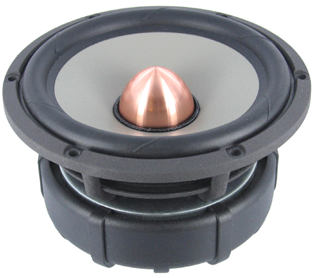
    A magnesium cone ~5.5” woofer from Seas. The distortion is low and it likes a small box. Excellent for our purposes here. The distortion does not look quite as low as the Scanspeak 15W but the Scanspeak would need a box ~4 times larger for the same bass output. The Seas W16 works better in a smaller box than the venerable W15. Distortion does rise above 1,000 Hz- something else to be kept in mind for the crossover. The metal cone gets floppy above 4,000 Hz so we will avoid that. Bonus: Many people love the Seas Excel drivers so I get to play with one here. Another bonus: The copper phase plug and this woofer, in general, look cool.

    Basic woofer: Seas ER15RLY (H1455), $82
    15 cm (5.5") cone driver, developed for use as a long throw high fidelity woofer or woofer/midrange unit. Edge coated reed/paper pulp cone, together with perfectly matched moving parts gives a smooth, extended frequency response.

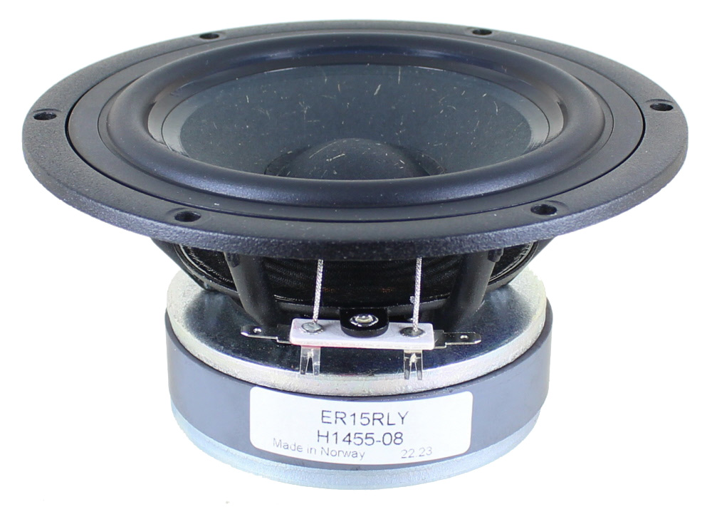
    In making a cheaper version of the speaker, I needed a woofer that would fit into the cabinet built for the W16 woofers. And I wanted to keep this woofer under $100. Some of the options, all from Seas, were the MCA15RCY, the L15RLY/P, the CA15RLY, and the ER15RLY. The MCA15 and the CA15 look to be older and I want to use drivers that will be around as long as possible, so all the design work here is useful for a while. The ER15 looks to be a decent, all around performer and it may be the newest of the bunch. Seems like a safe choice here.


    Cabinet design- Faceted and Slanted:
    For a prior project I made a small collection of test cabinets in various configurations to see the influence of cabinet shape on baffle diffraction. I came away thinking that one of the better cabinet configurations is to have facets cut into the cabinet and also have the front baffle slanted. If you want to see the measurements, the link is here:

    Start at post Firmware news... and then read onto the following page.

    A general discussion on methods for cutting facets can be found here:
    DIY (Do it yourself): Cabinetry, speakers, subwoofers, crossovers, measurements. Jon and Thomas have probably designed and built as many speakers as any non-professionals. Who are we kidding? They are pros, they just don't do it for a living. This has got to be one of the most advanced places on the net to talk speaker building, period.

    I’ll show details of how I cut the facets on my table saw for these mini MT’s. The smaller cabinet really made things much easier than the larger cabinets I tried earlier. If you want to try your hand at a faceted cabinet I recommend starting with something small.

    Here is a side view photo showing the angle of it all.

    Click image for larger version  Name:	DSC_0041sm_zpsdebdd595.webp Views:	7 Size:	25.7 KB ID:	931277


    Bass tuning and options:
    The sealed cabinets I made have an internal volume of 303 cubic inches or 5 liters before we subtract out the volume of the drivers and crossovers. I used WinISD to get a rough idea of bass output. No, it doesn’t provide a terribly accurate picture of what is really going on, especially when room interactions are there. But it’s a rough place to start. The F3 (-3 dB) point for the W16 in a cabinet of this small volume is at 80 Hz. Couple these with a sub and a prepro/receiver crossed at 80 Hz (or lower) and you will not be missing any output.

    If you want more bass extension out of these speakers, the W16 woofer can certainly provide it. Increase the volume or port them with increased volume. According to WinISD, you could get an F3 of 45 Hz from these if you roughly double the volume and add a port. I have no idea how realistic that is. But if you do want to increase the cabinet volume you can either add volume below the woofer, make them deeper, or even try both. However you must keep the front baffle exactly as shown. The facets, slant, width, height above the woofer, and tweeter position should not be changed. I will provide all of these details as the project progresses.


    Which speaker should I build?
    Some thoughts on the Deluxe (W16 woofer) versus the Basic (ER15 speakers).

    -I really do prefer the deluxes. The difference is not subtle. But both speakers came out well. Both sound very good. For me, I like the extra clarity, low distortion, and tighter bass that the W16 woofer offers. It’s a noticable difference. Although the ER15 is supposed to be pretty good. At ~$82 each it’s a driver in the high value range. I probably should have listened to the basics before the deluxes. So as not to be so spoiled. If you don’t hear the deluxes first, you might be OK. When I first heard the basics, I was underwhelmed. But then with the voicing, I brought them to life. They do sing well now.

    -The deluxes are going to be maybe $300-350 more per pair. (Specifics to follow, in the future.) That’s a lot. So don’t build the deluxes if it’s going to mean that your kids go hungry or you can’t make the rent.

    -The ER15 and the W16 woofers fit into the exact same cabinet hole. So you could start with the ER15’s and, some day, upgrade to the W16’s with the same cabinets. But the crossover changes, too.

    -The deluxes are easier for an amp to run, I found. When playing through a receiver, the deluxes played fine. As did the basics. But when the volume was turned up high, the basics shut down the receiver, putting it into protection mode. The deluxes did not do that. You might want to consider what you are using to drive the speakers before deciding on basics versus deluxe.

    -Bass extension. For these cabinets, the W16 modeled to reach deeper, solid to 80 Hz. The ER15 modeled to not go as deep, maybe only to 95 Hz or so. But I think that the near field measurements I took in the cabinets look as though both woofers hit 80 Hz prior to any roll off. I’ll post those plots overlayed with typical sub crossovers some day. For the moment, I would not let bass extension factor in to a basics versus deluxe decision.


    Project name- The Schlafmutze Mini MT’s:
    In keeping with my last project, the Spassvogels (a person who jokes around a lot, literally “joke bird”), we’ll go with another German nickname that my gal uses for me. When you wake up in the morning and look, ummm, not fully alive, in the US we might call you a “sleepy head.” In Germany they might call you a “Schlafmutze.” Translated literally it’s “sleep cap.” Caps are small, as are these speakers. So “Schlafmutze” is is.

    Here is another beauty shot of the Schalfmutze Basics, just for fun.

    Click image for larger version  Name:	DSC_0044sm_zps86b2b5af.webp Views:	7 Size:	37.9 KB ID:	931278

    OK, that’s the basic idea of the project. The cabinets are built. Measurements and crossover work are in progress, then voicing. I’ll post progress as it happens. So far, it's a really fun little project.
    Last edited by theSven; 25 June 2023, 17:38 Sunday. Reason: Remove broken image link
  • JonW
    Super Senior Member
    • Jan 2006
    • 1582

    #2
    Final crossover for the deluxe (W16 woofer), in room speakers

    The circuit:
    Click image for larger version  Name:	Slide1_zpsfcf38ae2.webp Views:	0 Size:	24.5 KB ID:	931328

    Both the tweeter (C2, C3, L2) and the woofer (L4, L5, C6) are third-order electrical filters. Acoustically, they both hit fourth-order Linkwitz-Riley (LR4).

    R2, R4, R8, and R9 are there to account for the DC resistance of the inductors. They are not physical parts of the crossover, so do not add them in. Using the small 18 and 20 gauge inductors, to fit into these tiny cabinets, makes for high DC resistance, so it’s been accounted for.

    R1 is a tweeter padding resistor. Changing the value here is an easy way to tune the speakers to have more or less treble. Add an Ohm for less treble, take one away for more. As it stands, there is a nice balance of highs versus mids. (Not much bass to speak of in these speakers.)

    The C5 cap helps kill the woofer resonance/floppiness around 5,000 Hz.

    There are two Zobels (C7, R11 and R12, C8 ) here. And an LCR filter (L1, C1, R3). Plus another filter (R10, L6). They each contribute a little bit with regard to keeping the frequency response flat and matching phase of the two drivers. Some of them help to keep the flattish impedance. I know that it’s a lot of parts, but they each really do help contribute to maximizing the performance of these drivers.


    Frequency response:
    These speakers sound best very flat. No smoothing here and they are almost at +/- 1 db.
    Click image for larger version  Name:	Slide2_zps4dc55ac2.webp Views:	0 Size:	37.3 KB ID:	931329


    Phase:
    Pretty well matched up.
    Click image for larger version  Name:	Slide3_zps4fa796ff.webp Views:	0 Size:	40.2 KB ID:	931330


    Impedance:
    It’s pretty smooth and flat, with no big peaks or swings above 100 Hz. That’s what I like to see. The lowest point is about 6 Ohms. These speakers are easier for an amp to drive than the Basics (details on those coming soon).
    Click image for larger version  Name:	Slide4_zps373eae40.webp Views:	0 Size:	41.5 KB ID:	931331


    Tweeter reverse null:
    Almost -30 db, which looks good to me.
    Click image for larger version  Name:	Slide5_zps450af5d9.webp Views:	0 Size:	39.1 KB ID:	931332


    Off-axis response:
    Using measurements taken 30 degrees horizontal.
    Click image for larger version  Name:	Slide6_zps8fe2a611.webp Views:	0 Size:	38.7 KB ID:	931333


    -=-=-=-=-=-=-=-=-=-=

    Final crossover for the deluxe (W16 woofer), on wall speakers


    Click image for larger version  Name:	Slide06_zpse2203817.webp Views:	0 Size:	20.7 KB ID:	931334

    Note that the only difference from the in room crossover is that the tweeter padding resistor, R1, has changed from 7 to 8 Ohms.

    Also note that resistors R2, R4, R8, and R9 are not physical parts of the crossover. I just added them into the circuit diagram to account for the DC resistance of the inductors.


    Frequency response:
    Click image for larger version  Name:	Slide04_zps37f57fca.webp Views:	0 Size:	31.7 KB ID:	931335


    Another view of the frequency response when the speakers are up against the wall. For this plot, I used measurement data taken for a longer period of time (9 ms), enough to see the effects of the wall bounce and cancellation nulls:
    Click image for larger version  Name:	Slide05_zpsda32338a.webp Views:	0 Size:	33.9 KB ID:	931336


    Phase of the on wall crossover with the on wall measurements:
    Click image for larger version  Name:	Slide07_zps4a6e09bc.webp Views:	0 Size:	31.8 KB ID:	931337


    Impedance of the on wall deluxe crossover:
    Click image for larger version  Name:	Slide08_zps3422a28c.webp Views:	0 Size:	34.0 KB ID:	931338


    Reverse tweeter null of the on wall measurements in the on wall crossover:
    Click image for larger version  Name:	Slide09_zps53d143c1.webp Views:	0 Size:	32.3 KB ID:	931339


    30 degrees off axis FR of the on wall measurements in the on wall crossover. Real 30 degree data were used (not a simulation):
    Click image for larger version  Name:	Slide10_zps1f41e43d.webp Views:	0 Size:	32.6 KB ID:	931340


    -=-=-=-=-=-=-=-=-=-=

    Final crossover for the basic (ER15 woofer), in room speakers

    NOTE: This crossover was changed to what is posted below on July 27, 2014.

    The general crossover topology here is generally similar to the deluxes. But they sound a little different and some things changed. This ER15 woofer needed more work to sound good than the W16. Let’s walk through it all.

    The basic, in room crossover:
    Click image for larger version  Name:	Slide1_zps641b7ede.webp Views:	0 Size:	20.3 KB ID:	931341

    R1 is a tweeter padding resistor. Adjust it to taste, to get more or less treble. I like it where it is at 3 Ohms.

    The electric filters for the tweeter (C2, C3, L2) and woofer (L4, L5, C6) are electrical third-order. Acoustically, they came out right at LR4.

    The Zobels (C7, R11 and R12, C8 ) and filters (L1, C1, R3 and R10, C9, L6) all helped bring things under control and sound good.

    The resistors R2, R4, R8, and R9 are not real. Do not add them in. They are there to account for the high DC resistance created by using these small 18 and 20 gauge inductors, needed to fit the crossovers into the tiny cabinets.

    Lots of parts but I think that they turned out sounding good.


    Final frequency response. No smoothing was applied and it’s just about +/- 2 dB:
    Click image for larger version  Name:	Slide2_zpsf49121ff.webp Views:	0 Size:	30.4 KB ID:	931342


    Phase. Looks like a good match to me:
    Click image for larger version  Name:	Slide3_zps72032c87.webp Views:	0 Size:	30.6 KB ID:	931343


    Impedance. I’m pretty happy with it but some amps may need to watch out for that dip to ~4 Ohms in the middle:
    Click image for larger version  Name:	Slide4_zpseeb0dd85.webp Views:	0 Size:	34.0 KB ID:	931344


    Reverse tweeter null:
    Click image for larger version  Name:	Slide5_zps82c0b1ef.webp Views:	0 Size:	31.1 KB ID:	931345


    Measurements taken 30 degrees off axis and put into the in room crossover:
    Click image for larger version  Name:	Slide6_zpsebffd9bb.webp Views:	0 Size:	32.1 KB ID:	931346


    -=-=-=-=-=-=-=-=-=-=

    Final crossover for the basic (ER15 woofer), on wall speakers


    Circuit for the on wall crossover:
    Click image for larger version

Name:	Slide06_zps24cdbf7a.webp
Views:	225
Size:	21.2 KB
ID:	931347

    It is the same as the in room crossover except for the tweeter padding resistor (R1) going from 3 Ohms before to 4 Ohms here. Remember that R2, R4, R8, and R9 are not physical parts of the crossover. They are just accounting for the DC resistance of the inductors.


    On wall measurements placed into the on wall crossover:
    Click image for larger version

Name:	Slide04_zpsb816273c.webp
Views:	221
Size:	30.8 KB
ID:	931348


    On wall measurements taken long enough (9 ms) to see the wall bounce and nulls, placed into the on wall crossover:
    Click image for larger version

Name:	Slide05_zpsd65da5b7.webp
Views:	199
Size:	33.9 KB
ID:	931349


    Phase of the on wall measurements in the on wall crossover:
    Click image for larger version

Name:	Slide07_zpsfceb15db.webp
Views:	221
Size:	32.2 KB
ID:	931350


    Impedance of the on wall crossover:
    Click image for larger version

Name:	Slide08_zpseb4ca6e8.webp
Views:	220
Size:	33.9 KB
ID:	931351


    Reverse tweeter null for on wall measurements in the on wall crossover:
    Click image for larger version

Name:	Slide09_zps8da4af26.webp
Views:	221
Size:	31.7 KB
ID:	931352


    30 degree off axis, on wall measurements in the on wall crossover:
    Click image for larger version

Name:	Slide10_zps83284cef.webp
Views:	228
Size:	32.6 KB
ID:	931353
    Last edited by theSven; 02 April 2023, 10:38 Sunday. Reason: Update image location

    Comment

    • JonW
      Super Senior Member
      • Jan 2006
      • 1582

      #3
      [[saved for BOM’s and variations]]

      Comment

      • JonW
        Super Senior Member
        • Jan 2006
        • 1582

        #4
        Building the cabinets:

        Here’s a tutorial on how I built the cabinets. There are probably plenty of other ways that you could go about it.

        I used 3/4” Baltic birch plywood for everything except for the front baffle, which is 1” thick. Alternatively you could probably be just fine with a standard 3/4” thick front baffle, given how small the cabinets are. The 1” front might help a little with minimizing cabinet resonance from the drivers moving in and out. With a cabinet this small I don’t think there’s any real need for braces. Again, due to the size, you might be able to get away using a real hard wood like a nice maple, cherry or oak. Then you would not need to veneer. And there’s nothing prettier than real wood. I’d consider real wood if I were to repeat this build, although I’d want to consult the woodworking experts first.

        Cutting facets can be challenging if, like me, you don’t have much for woodworking skills. We had a discussion here on various ways to cut facets:

        DIY (Do it yourself): Cabinetry, speakers, subwoofers, crossovers, measurements. Jon and Thomas have probably designed and built as many speakers as any non-professionals. Who are we kidding? They are pros, they just don't do it for a living. This has got to be one of the most advanced places on the net to talk speaker building, period.


        For the Schlafmutzes life is pretty easy, relatively speaking. The cabinets are quite small and that just made it all significantly less effort than when I built the larger, floorstanding cabinets for the Spassvogels. Here I was able to do everything on the table saw. It was quicker, easier, and more precise than using the circular saw for the larger facets of the Spassvogels.

        Here are all the dimensions you will need:
        Click image for larger version  Name:	FrontDimensSchlaffmutze2.webp Views:	0 Size:	21.8 KB ID:	931355

        Click image for larger version  Name:	SideDimensSchlafmutze2.webp Views:	0 Size:	24.9 KB ID:	931356


        And here’s a step-by-step procedure for how I made them…

        -Start by gluing up some birch plywood to 1” thickness for the front baffles. I glued together some 3/4” and 1/4”.

        -Cut the baffles to the appropriate size of 6.5 x 10.5”. Remember: Have the tops and bottoms cut at the 8.5 degree angle, as you can see here:
        Click image for larger version  Name:	85_DegreeEdges.webp Views:	0 Size:	7.4 KB ID:	931357

        -Mark up the baffles for all the facets and driver cutouts. Remember: The tweeter holes will be offset from the center line 9/16” to make mirror images, one left and one right. The pin holes for your Jasper jig will be 3 5/8” from the bottom for the woofer and 8 1/2” from the bottom for the tweeter. For the top left and right facets they will be 4 1/2” long and 1/2” in from the edges. The bottom facets are 3/8” in from the sides and run up 2 3/4”.
        Click image for larger version  Name:	MarkedForCuts.webp Views:	0 Size:	6.7 KB ID:	931358

        -Set up to cut the top right facet. Put your saw blade at 45 degrees for all the facet cuts. My table saw has a nice sliding miter table so I have the guide set at 7 degrees for the cut here. The work piece is thus rotated 7 degrees from the blade. For this facet cut I have the miter table to the right of the blade. Align the close edge of the blade with the cut line you marked. With the saw still off, push the work piece up to the blade to make sure that the blade will cut right on the facet line you marked earlier. Here’s how I arranged it before:
        Click image for larger version  Name:	CutTopR_FacetBefore.webp Views:	0 Size:	15.0 KB ID:	931359

        -And here is after the cut:


        -Then do the top left facet as shown. Note that the guide is still at a 7 degree angle but it is 7 degrees back from the perpendicular mark. Whereas for the top right facet cut the guide was 7 degrees forward from the perpendicular mark.
        Click image for larger version  Name:	CutTopR_FacetAfter.webp Views:	0 Size:	9.0 KB ID:	931360

        -The top facet is an easy cut with the guide now perpendicular to the blade:
        Click image for larger version  Name:	CutTopFacet.webp Views:	0 Size:	12.9 KB ID:	931361

        -Repeat for the bottom left and right facets to make the 5 total facet cuts. These bottom facets are only there for aesthetics- they should not influence the sound. Feel free to skip the bottom facets if you prefer or are making the cabinets lower for more bass extension. I made the bottom facets smaller than the tops so the table saw sliding guide was likely at a different angle than that used to cut the tops. After all 5 facets are cut they will look like this:
        Click image for larger version  Name:	FacetsDone.webp Views:	0 Size:	10.0 KB ID:	931362

        -Cut the driver holes and the rabbets for flush mounting. Remember: Make a left and a right, mirror images for the tweeter offset from the center line. Here is what I did…

        -For the tweeter hole you may have to differ from your usual procedure. The tweeter is pretty small and so a Jasper jig won’t allow you to cut a small enough hole for the tweeter rear. So I started by making the rabbet for flush mounting. You can use the Jasper jig for this part. I made a 2 1/2” diameter cut with the Japser jig but only cut 3/16” deep. Actually, I used a 1/2” diameter router bit with the jig and so the pin was placed in the 2 1/4” marked hole. Then I just made one pass with the router to get the rabbet. Next I used a 1 7/8” Forstner bit in a drill press to cut a hole in the middle of the rabbet that was made with the Jasper jig. At this point cutting the tweeter hole is done.

        -For the woofer I made a 4 15/16” hole with the Japser jig. Then I used a 3/8” rabbet bit in the router to make the rabbet for flush mounting the woofer.

        -Your baffle with the facets and driver holes will then look like this:
        Click image for larger version  Name:	DriverHolesRabbets.webp Views:	0 Size:	13.9 KB ID:	931363

        -Use a 45 degree chamfer bit in your route and chamfer the inside of the woofer mounting hole. Taking away that bit of wood helps the woofer to breathe better which is especially good for a woofer like the W16 with such a constricted rear construction. I don’t have a photo of this step but it’s a very common thing to do in other speaker builds.

        -Cut the notches out of the tweeter hole/rabbet to allow space for the tweeter leads. Do not cut all the way to the edge of the rabbet or you will be able to see that later. You do not need to cut notches for this woofer. Just give a little bend to each woofer lead and the driver will fit into the hole.

        -Now is a good time to drill your pilot holes for the screws to hold in the drivers. Before deciding where to put the pilot holes, look below at how the felt will be installed. You will want the woofer leads to be facing the bottom of the cabinet. Locate your pilot holes accordingly.

        -To make the sides, rip some strips of wood (2 per speaker) to 6 3/4” width. Then cut the ends at the 8.5 degree angle. Your saw blade is perpendicular to the table and the miter guide is at the 8.5 degree angle. In the end you’ll have the side pieces at the same 10 1/2” height as the front baffle.

        -For the tops and bottoms rip some wood to 5 1/16” wide. Cut the ends with the table saw blade at a 8.5 degree tilt.

        -Make the rear baffle from a 6 1/2” wide strip of ply to be 10 1/2” long. Cut the ends with the blade at the 8.5 degree angle.

        -Glue on the sides, top, bottom onto the front baffle. After that dries, glue on the rear. Remember: Make everything at the 8.5 degree slant. I made the rear baffle parallel to the front baffle and the top parallel to the floor, although you do not have to do it that way.
        Click image for larger version  Name:	BoxComplete.webp Views:	0 Size:	9.6 KB ID:	931364

        -Glue on the veneer.

        -A tip I found for veneering: Trimming the veneer of the facets can be difficult because, when you get down to where the facets narrow to the tip, you are often cutting against the grain on both sides. And with cabinets and facets this small the main piece of veneer on the facet has little contact area and, hence, little adhesion. I did my trimming with a fixed blade utility knife. The facet veneer pieces kept falling off the cabinet. So for the facets I actually used super glue to attach the veneer. Then the trimming went well, the veneer stayed on the cabinet.

        -Drill your holes for the binding posts. I drilled the holes at an 8.5 degree angle from the rear baffle such that the binding posts will be parallel to the floor. Fancy, eh?

        -Put on your finish coats.

        -Install foam weather stripping or gasket foam around the driver hole rabbets, poke holes in the foam for the pilot holes, and also put in the binding posts.

        Click image for larger version  Name:	DSC_0028sm_zps3a447d9a.webp Views:	0 Size:	26.1 KB ID:	931365

        -In the end the cabinets might look something like this:
        Click image for larger version  Name:	MT_FinishDone.webp Views:	0 Size:	40.2 KB ID:	931366

        -Another build tip: I found the leads of the tweeter to feel like something was going to fall off, from the wires pulling on the leads. So I soldered on the wire and then used electrical tape to wrap the wires to the tweeter tightly, as shown below. When putting the tweeters into the cabinet and moving the wires around, I think that the tape will help.

        Click image for larger version  Name:	DSC_0030sm_zpsb542d8ff.webp Views:	0 Size:	26.6 KB ID:	931367

        -Yet another build tip: The tweeter requires very tiny screws. Tiny screws tend to be short and I wanted something as substantial as possible to bite into the wood. The best I could find was Groups x 3/4” Phillips pan heads from McMaster-Carr. Madisound also sells M3 hex head screws, specifically for these small Scanspeak tweeters but they are only 0.6” long so I went with the longer 3/4” #4’s.

        Adding felt:
        There might be some cabinet reflections happening inside, so the helpful advice was to add felt and absorb things up. The measurements indicated a little help from the felt. Here is what I did and also what I recommend others do if they are going to build these speakers. I used F-13 felt, 1/4” thick and 2” wide strips purchased from McMaster-Carr. 3 feet should be plenty for 2 speakers. It’s about $3 plus shipping. Maybe order this with the various black screws that you will need for fastening the drivers to the cabinets.
        Click image for larger version  Name:	DSC_0280sm_zps42260364.webp Views:	0 Size:	28.1 KB ID:	931368

        The W16 woofer has a rubber boot on the back. Peel it off. Don’t worry. It comes off easily. The ER15 woofer does not have this boot so no need to remove it. Otherwise, do everything the same as shown here for the W16.
        Click image for larger version  Name:	DSC_0281sm_zps41f0432c.webp Views:	0 Size:	34.2 KB ID:	931369

        See. It’s off.
        Click image for larger version  Name:	DSC_0282sm_zpse7678da6.webp Views:	0 Size:	30.1 KB ID:	931370

        Cover the back with felt. I used one strip (2” wide) and then another strip that was cut to half width (1”). I glued the felt to the driver using hot melt adhesive. It stuck very well.
        Click image for larger version  Name:	DSC_0283sm_zpsd59459d1.webp Views:	0 Size:	36.5 KB ID:	931371

        Then cut a strip of felt that will wrap about 2/3 of the way around the magnet. We do not want to wrap around the entire magnet or else the assembly won’t fit through the cabinet hole. I also have the woofer leads on the bottom here, in the area not covered by the felt. You might want to have your cabinet pilot holes for the woofer screws drilled and positioned with all of this in mind.
        Click image for larger version  Name:	DSC_0284sm_zps34bacc41.webp Views:	0 Size:	38.8 KB ID:	931372

        I also glued down, with hot melt adhesive, a strip of felt on the bottom of the cabinet, touching the front.
        Click image for larger version

Name:	DSC_0285sm_zpsedc99c34.webp
Views:	221
Size:	25.5 KB
ID:	931373

        After gluing the felt to the magnet, here is what it looks like.
        Click image for larger version

Name:	DSC_0286sm_zps8e75386e.webp
Views:	227
Size:	23.9 KB
ID:	931374

        Click image for larger version

Name:	DSC_0287sm_zpsc871c4b6.webp
Views:	221
Size:	29.7 KB
ID:	931375


        Adding more sound absorption:
        The small size of these speakers requires a little more material to calm down internal reflections. Details about how this helped both the measurements and voicing/sound of the speakers are later in this thread. You’ll want to add a piece of Parts Express 1.25” thick Sonic Barrier. I used a piece to cover the whole rear of the cabinet except for a section cut out to make room for the binding posts (I have 4 binding posts.), about 5” x 9”. The Sonic Barrier is $27 per sheet and one sheet should be enough for 4 pairs of speakers. This Sonic Barrier is in addition to the felt, shown above.

        Click image for larger version

Name:	DSC_0288sm_zpsddcc95ba.webp
Views:	231
Size:	50.6 KB
ID:	931376

        Click image for larger version

Name:	DSC_0002sm_zpsf682c03d.webp
Views:	287
Size:	25.0 KB
ID:	931377
        Last edited by theSven; 02 April 2023, 10:50 Sunday. Reason: Update image location

        Comment

        • JonW
          Super Senior Member
          • Jan 2006
          • 1582

          #5
          [[saved for, Idunno, something else that I probably forgot about]]

          Comment


          • theSven
            theSven commented
            Editing a comment
            Safe to say 10 years later you forgot :-)
        • Hdale85
          Moderator Emeritus
          • Jan 2006
          • 16075

          #6
          They're so cute lol. That tweeter is quite popular for car audio.

          Comment

          • JonMarsh
            Mad Max Moderator
            • Aug 2000
            • 15277

            #7
            I'll be very curious to see how these work out for you, Jon! They remind me a little in concept of the small stand mounted NHT's that I've never gotten around to building crossovers for! I've got some small SS tweeters, too, natch. I've also just received some SB Acoustics small form factor tweeters that look very promising ; I should probably probably have a shoot out! These must be why you need small caps and coils!
            the AudioWorx
            Natalie P
            M8ta
            Modula Neo DCC
            Modula MT XE
            Modula Xtreme
            Isiris
            Wavecor Ardent

            SMJ
            Minerva Monitor
            Calliope
            Ardent D

            In Development...
            Isiris Mk II updates- in final test stage!
            Obi-Wan
            Saint-Saëns Symphonique/AKA SMJ-40
            Modula PWB
            Calliope CC Supreme
            Natalie P Ultra
            Natalie P Supreme
            Janus BP1 Sub


            Resistance is not futile, it is Volts divided by Amperes...
            Just ask Mr. Ohm....

            Comment

            • JonW
              Super Senior Member
              • Jan 2006
              • 1582

              #8
              Originally posted by Hdale85
              They're so cute lol. That tweeter is quite popular for car audio.
              Thanks. They are kind of cute. And so much easier to move around and work with than floorstanders. The W16 flavor is quite heavy. I'll have to weight it, but without a crossover they might be pushing 20 pounds/9 kg each.

              I didn't know about the tweeter being used in car audio. Interesting.

              Comment

              • JonW
                Super Senior Member
                • Jan 2006
                • 1582

                #9
                Originally posted by JonMarsh
                I'll be very curious to see how these work out for you, Jon! They remind me a little in concept of the small stand mounted NHT's that I've never gotten around to building crossovers for! I've got some small SS tweeters, too, natch. I've also just received some SB Acoustics small form factor tweeters that look very promising ; I should probably probably have a shoot out! These must be why you need small caps and coils!
                Thanks, Jon. I'm also curious to see how they turn out. And yup, this is the project for which I was asking about small caps and coils.

                Right, I remember those NHT's. I could never get by the color of those. On their own, they are nice looking. But they reminded me too much of my great aunt's bathroom. I visited there a lot when I was a little kid, in the 1970's. Her bathroom had a toilet and sink of the exact same burgundy color as those NHT's. Well, I guess that I would have bought them if I were looking for speakers for her bathroom.

                I didn't know that SB also had a small tweeter these days. I have not yet worked with any of their drivers, but it sure looks like they are making good stuff. I was really happy with the Scanspeaks of my last project and this tweeter measured quite well by Zaph. So it looked like a good candidate for this project here. I'm very curious to see how the metal coned W16 sounds versus the paper/reed ER15. The crossovers will influence (or even totally dictate) my listening impressions. But when taking the measurements, the MLS "phssst" pulse sounded very different between the two woofers. Really different.

                Comment

                • Hdale85
                  Moderator Emeritus
                  • Jan 2006
                  • 16075

                  #10
                  Yeah pretty much any high end tweeter that has a small face has/is being used in DIY car audio builds.

                  Comment

                  • JonW
                    Super Senior Member
                    • Jan 2006
                    • 1582

                    #11
                    Originally posted by Hdale85
                    Yeah pretty much any high end tweeter that has a small face has/is being used in DIY car audio builds.
                    I guess that makes sense. My car is now 12 years old and one speaker has blown. I looked into upgrading the speakers and such. Car audio is a totally different world. I guess my car has a non-standard system so it is hard to deal with unless you're up for ripping everything out and starting from scratch. I'd rather spend my time on speakers for the house and office that I will, most likely, have around longer than my car.

                    Comment

                    • JonW
                      Super Senior Member
                      • Jan 2006
                      • 1582

                      #12
                      Here are some photos from the measurements session. I find taking measurements to be one of the painful parts of speaker design. So many places for things to go wrong. But this time, all went mostly well. I had a little trouble collecting the impedance data. I’ll post details on that after I make up some graphs. Overall, though, things went smoothly and I’m happy.

                      It was interesting hearing the difference between the W16 and the ER15 woofers. When the MLS pulse made the “phssst” sound, the paper coned ER15 sounded full and rich. The metal coned W16 sounded kind of metallic, thin, and plinky. I’m curious to see how they each sound with crossovers and music.

                      A Deluxe W16 speaker for in room measurements:

                      Click image for larger version  Name:	DSC_0053sm_zpscb29eb43.webp Views:	117 Size:	39.5 KB ID:	931378

                      Taking measurements with the speaker on wall:

                      Image not available

                      On wall and off axis:

                      Image not available
                      Last edited by theSven; 25 June 2023, 17:41 Sunday. Reason: Remove broken image links

                      Comment

                      • technodanvan
                        Super Senior Member
                        • Nov 2009
                        • 1012

                        #13
                        I really, really like the size of these little guys. Looking forward to see just how you manage to cram the crossover inside!
                        - Danny

                        Comment

                        • ---k---
                          Ultra Senior Member
                          • Nov 2005
                          • 5202

                          #14
                          These aren't done yet? :P

                          Just giving you a hard time. They look great and you're making progress. That's what matters. And making full professor since you started. Big time thumbs up. You should include your little helper in some of your photos. We probably wouldn't be as hard on you.
                          - Ryan

                          CJD Ochocinco! ND140/BC25SC06 MTM & TM
                          CJD Khanspires - A Dayton RS28/RS150/RS225 WMTMW
                          CJD Khancenter - A Dayton RS28/RS150/RS180 WTMW Center

                          Comment

                          • Hdale85
                            Moderator Emeritus
                            • Jan 2006
                            • 16075

                            #15
                            How are these near field? Like computer use and what not?

                            Comment

                            • JonW
                              Super Senior Member
                              • Jan 2006
                              • 1582

                              #16
                              Originally posted by Hdale85
                              How are these near field? Like computer use and what not?
                              Yeah, that's the idea. But I think that "near field" does not mean much with regard to speaker design. The radiating area of all the drivers should probably be small. So no floor-to-ceiling arrays and such. Otherwise, I think it's just supposed to be a generally well designed speaker. We shall see!

                              Comment

                              • JonW
                                Super Senior Member
                                • Jan 2006
                                • 1582

                                #17
                                Originally posted by ---k---
                                These aren't done yet? :P

                                Just giving you a hard time. They look great and you're making progress. That's what matters. And making full professor since you started. Big time thumbs up. You should include your little helper in some of your photos. We probably wouldn't be as hard on you.
                                Hey Ryan,

                                Well, you have a kid and then we'll see how rapidly your speaker building progresses. :P Actually, after not touching the speakers for a long time, it's quite refreshing to be back at it. The hobby is fun. I'm already starting to think about my next project.

                                Comment

                                • JonW
                                  Super Senior Member
                                  • Jan 2006
                                  • 1582

                                  #18
                                  Originally posted by technodanvan
                                  I really, really like the size of these little guys. Looking forward to see just how you manage to cram the crossover inside!
                                  Thanks. Yeah, there will not be much space in there. It gives me incentive to keep the crossover really simple. I'll post the crossover ideas as they come up. At the moment, for the Deluxe In Room flavor, I'm trying to hit an LR2 crossover and I have it down to second order electrical on the tweeter with a padding resistor and an LCR circuit to flatten the impedance. The woofer is first order electrical with only a cap to kill the metal cone floppiness. I'm also working on an LR4 version that has more parts, taking up more space, but the plots may be a little prettier. Voicing will tell. There is still a lot of work to do there before I post preliminary, non-voiced crossovers. Not to mention crossovers for the other flavors of the speakers.

                                  Comment

                                  • JonMarsh
                                    Mad Max Moderator
                                    • Aug 2000
                                    • 15277

                                    #19
                                    Originally posted by JonW
                                    Thanks. Yeah, there will not be much space in there. It gives me incentive to keep the crossover really simple. I'll post the crossover ideas as they come up. At the moment, for the Deluxe In Room flavor, I'm trying to hit an LR2 crossover and I have it down to second order electrical on the tweeter with a padding resistor and an LCR circuit to flatten the impedance. The woofer is first order electrical with only a cap to kill the metal cone floppiness. I'm also working on an LR4 version that has more parts, taking up more space, but the plots may be a little prettier. Voicing will tell. There is still a lot of work to do there before I post preliminary, non-voiced crossovers. Not to mention crossovers for the other flavors of the speakers.
                                    Quasi series network, like the NatlieP, might help- depending on how compatible the drivers are- without the metal cone peaks, they can be a lot simpler than what I had to do.

                                    When you get data files, send them to me if you want to laugh at some outside meddling!
                                    the AudioWorx
                                    Natalie P
                                    M8ta
                                    Modula Neo DCC
                                    Modula MT XE
                                    Modula Xtreme
                                    Isiris
                                    Wavecor Ardent

                                    SMJ
                                    Minerva Monitor
                                    Calliope
                                    Ardent D

                                    In Development...
                                    Isiris Mk II updates- in final test stage!
                                    Obi-Wan
                                    Saint-Saëns Symphonique/AKA SMJ-40
                                    Modula PWB
                                    Calliope CC Supreme
                                    Natalie P Ultra
                                    Natalie P Supreme
                                    Janus BP1 Sub


                                    Resistance is not futile, it is Volts divided by Amperes...
                                    Just ask Mr. Ohm....

                                    Comment

                                    • JonW
                                      Super Senior Member
                                      • Jan 2006
                                      • 1582

                                      #20
                                      Originally posted by JonMarsh
                                      Quasi series network, like the NatlieP, might help- depending on how compatible the drivers are- without the metal cone peaks, they can be a lot simpler than what I had to do.

                                      When you get data files, send them to me if you want to laugh at some outside meddling!
                                      Hi Jon,

                                      Cool. I’ll take you up on that offer. But only if you have time for it. It will be interesting to see how your crossover might come out compared to my pathetic attempt. Don’t let my faux erudite typing mislead you. I really have very little idea how to make a crossover. But I have fun trying.

                                      I need to crunch through the measurement data a bit. I’ll post a few plots here. Get a little farther along with my preliminary crossover(s), post those, then I’ll dig out the files and email them to you. (Is email best?) Maybe best of all, I’ll study how you approached the Nat P crossover. I’m sure to learn something.

                                      OK, here is the start of the measurement data that I got. For some reason, things were generally noisier than for my last project. The microphone probably picked up the voices in my head. The impedance measurements came out kind of funny but I think that they will be OK, in the end. Below is what I got for the two drivers. Noisy and an odd slope downward at the high frequencies.

                                      Click image for larger version  Name:	TampW_Impedance_zps11e204e2.webp Views:	65 Size:	8.1 KB ID:	931379

                                      And here is what I got as a “blank” measurement with no drivers. Even though I calibrated everything. Hmmm.

                                      Image not available

                                      It’s not pretty. OK, it’s downright ugly. But I think that it’ll be OK. I just need to know where the impedance peaks are and work with those. Plus I’ll check to see if there is any rising impedance from the tweeter, relative to that background plot, at the high frequencies and whether or not a Zobel should be considered.

                                      More plots are on the way. Not sure when. Then some early looks at crossovers. And then I’ll email some data. Oh, there will be 4 versions of the speakers (metal W16 versus paper ER15 woofers and both on wall versus in room). I’m starting with the W16 in room flavor, figuring that’s the main version. I’ll email those files unless you want others or all of them.
                                      Last edited by theSven; 25 June 2023, 17:42 Sunday. Reason: Remove broken image link

                                      Comment

                                      • cjd
                                        Ultra Senior Member
                                        • Dec 2004
                                        • 5568

                                        #21
                                        you wouldn't happen to have phantom power on a port you're using for impedance? I've done that with similar results. That data looks bad enough I'd not use it.
                                        diVine Sound - my DIY speaker designs at diVine Audio

                                        Comment

                                        • JonW
                                          Super Senior Member
                                          • Jan 2006
                                          • 1582

                                          #22
                                          Originally posted by cjd
                                          you wouldn't happen to have phantom power on a port you're using for impedance? I've done that with similar results. That data looks bad enough I'd not use it.
                                          Hi Chris,

                                          Thanks. Yeah, there is phantom power. I'm using an M Audio Mobile Pre USB for a sound card. You can see it in the measurement photos above in post #12. It's the silver box on top of the black box in the middle photo. It has phantom power and that's what I used to power the microphone. I left the phantom power on for the impedance measurements. Could that have been a problem? I don't think that it was for my last project. I find measurements to be difficult- there are so many places to screw something up. Although, in principle, the ideas behind it all are pretty easy.

                                          I think that the measurements are OK to use. I'm finding that the impedance peaks vary a lot with changes to the crossover, just as they should. The only major problems are that the plots are noisy and that there is that downward slope at high frequencies. The noise is not a big deal. And the slope isn't great, but I think that I just need to keep checking how the total impedance changes relative to the raw drivers. If it rises on the high end, I'll consider a Zobel.

                                          I'll post more measurement and preliminary crossover pictures in the coming days. On the plus side, I have a dedicated laptop for only speaker measurements and crossover design. On the minus side, it's 11+ years old (which is why I have it) and does not have a wireless card. So transferring and then posting plots takes a little effort.

                                          Comment

                                          • cjd
                                            Ultra Senior Member
                                            • Dec 2004
                                            • 5568

                                            #23
                                            Originally posted by JonW
                                            Thanks. Yeah, there is phantom power. I'm using an M Audio Mobile Pre USB for a sound card. You can see it in the measurement photos above in post #12. It's the silver box on top of the black box in the middle photo. It has phantom power and that's what I used to power the microphone. I left the phantom power on for the impedance measurements. Could that have been a problem?
                                            Absolutely. I use an M-Audio external sound card also (mine is blue) and the phantom power absolutely was the cause of oddities in impedance measurements for me - and the data was off enough to alter results in simulation.

                                            C
                                            diVine Sound - my DIY speaker designs at diVine Audio

                                            Comment

                                            • JonW
                                              Super Senior Member
                                              • Jan 2006
                                              • 1582

                                              #24
                                              Originally posted by cjd
                                              Absolutely. I use an M-Audio external sound card also (mine is blue) and the phantom power absolutely was the cause of oddities in impedance measurements for me - and the data was off enough to alter results in simulation.

                                              C
                                              Thanks for the tip! So what is the solution? Maybe the impedance measurements will work OK with the phantom power switch turned off? Perhaps it's only needed to be on when running the microphone, which is not used for the impedance measurements?

                                              The good news here is that I think the data will work out OK. The peaks do change with the crossover. For example, I had a big tweeter impedance peak in a crossover. I added an LCR filter to flatten it and, sure enough, it flattened out.

                                              Comment

                                              • cjd
                                                Ultra Senior Member
                                                • Dec 2004
                                                • 5568

                                                #25
                                                Phantom power is only needed for the microphone.

                                                The measurements you have aren't total fiction, so yes - they'll respond to things like an LCR. However, they're wrong. The mid-woofer looks very wrong well below the intended crossover point, and the crossover acts directly on impedance. It should be a rising impedance above 1kHz, and instead it's dropping.

                                                I understand the reticence to re-do the measurements, but I really can't recommend assuming what you have is usable.

                                                C
                                                diVine Sound - my DIY speaker designs at diVine Audio

                                                Comment

                                                • JonW
                                                  Super Senior Member
                                                  • Jan 2006
                                                  • 1582

                                                  #26
                                                  Originally posted by cjd
                                                  Phantom power is only needed for the microphone.

                                                  The measurements you have aren't total fiction, so yes - they'll respond to things like an LCR. However, they're wrong. The mid-woofer looks very wrong well below the intended crossover point, and the crossover acts directly on impedance. It should be a rising impedance above 1kHz, and instead it's dropping.

                                                  I understand the reticence to re-do the measurements, but I really can't recommend assuming what you have is usable.

                                                  C
                                                  Thanks, Chris. I see what you are saying. I wonder if anyone out there would agree or not. Given that I think it might be workable, if I look for changes relative to the starting drivers alone.

                                                  Yeah, redoing the measurements is a lot more onerous than it used to be for me. With a little kid running around the house, I no longer have a room in which I can set up the measurement system and leave it there. So redoing the measurements will require collecting all the gear, setting it up, getting the system to work properly, taking the measurements, then breaking everything down and putting it away. And it all has to be done at once, with the kid. That's probably a 6 hour block of free time, which is almost unheard of in my life these days, between the kid and work. But if I really need to do it, I will.

                                                  I do think, however, that I will get some time, here and there, to work on the preliminary crossovers this weekend. Some quality time with LspCAD. I'm really looking forward to that. If I do get to make some progress there, I'll post where I get.

                                                  If anyone else has an opinion regarding the impedance measurements, I'd love to hear it.

                                                  Comment

                                                  • ---k---
                                                    Ultra Senior Member
                                                    • Nov 2005
                                                    • 5202

                                                    #27
                                                    If you just need impedance, spend $100 and get the Woofer Tester from PE. Wouldn't have to make any mess and could probably be done in less than 30 mins. If you want to swing by Chicago, I would even let you borrow mine.
                                                    - Ryan

                                                    CJD Ochocinco! ND140/BC25SC06 MTM & TM
                                                    CJD Khanspires - A Dayton RS28/RS150/RS225 WMTMW
                                                    CJD Khancenter - A Dayton RS28/RS150/RS180 WTMW Center

                                                    Comment

                                                    • 5th element
                                                      Supreme Being Moderator
                                                      • Sep 2009
                                                      • 1671

                                                      #28
                                                      As has been mentioned the impedance measurements that you've done are so far off as to be useless. I mean they will let you see what frequency the box is tuned to, but that's about it.

                                                      For impedance measurements though, you shouldn't need to move much around at all. All you need is the laptop, m audio soundcard, an amplifier, the measurement jig and the loudspeaker. Your listening room presumably has an amp and the speakers are small enough to move around as is necessary, so put them on top of your other loudspeakers as above, and take the laptop to them. I can't see that being too difficult or time consuming really.

                                                      If you really don't want to take measurements again then use SPLtrace with the graphs from SEAS and Speak. Your tweeter should measure almost identical to what Scan measure and the impedance that SEAS will have measured on the mid/bass should be virtually identical to your measurements from about 200Hz and up. The only thing different for both drivers would be a slightly different fs on the tweeter and a different low end impedance on the mid/bass due to the alignment of the box. Both of these differences should be far enough away from the xover frequency such that they will have very little impact on the end design.
                                                      What you screamin' for, every five minutes there's a bomb or something. I'm leavin' Bzzzzzzz!
                                                      5th Element, otherwise known as Matt.
                                                      Now with website. www.5een.co.uk Still under construction.

                                                      Comment

                                                      • JonW
                                                        Super Senior Member
                                                        • Jan 2006
                                                        • 1582

                                                        #29
                                                        Thanks for the help, fellas. It looks like I need to remeasure the impedance. Ugh. Maybe it won’t take too long, given that I have done it recently and my mind is fresh on it. Well, you know. A fresh mind for me. Not a fresh mind in the absolute sense.

                                                        For my last project, when voicing potential crossovers, I found that flattening a peak in the impedance did help the sound a bit. So impedance is important to get right. (Duh, I know.)


                                                        Originally posted by ---k---
                                                        If you just need impedance, spend $100 and get the Woofer Tester from PE. Wouldn't have to make any mess and could probably be done in less than 30 mins. If you want to swing by Chicago, I would even let you borrow mine.
                                                        Thanks Ryan! I’ll probably see if I can get the impedance data from my current system without too much of a time burn. It should work fine. It's just a time issue.


                                                        Originally posted by 5th element
                                                        I can't see that being too difficult or time consuming really.
                                                        I’m going to go out on a limb here and guess that you don’t have a toddler running around the house. Plus both you and a spouse with ~80 hour/week jobs. You know, just a guess. :P

                                                        Comment

                                                        • JonW
                                                          Super Senior Member
                                                          • Jan 2006
                                                          • 1582

                                                          #30
                                                          Here are some SPL measurements. They look a lot better than the impedance plots. The data are all shown raw, no smoothing.

                                                          The W16 woofer in the middle of the room versus on a wall:
                                                          Click image for larger version

Name:	W_OnWall_vs_InRoom_zps4ac93427.webp
Views:	145
Size:	14.4 KB
ID:	931380

                                                          Notice the big dips at ~300 Hz and ~800 Hz. I will post a step-by-step build process for the speakers in the future. But you can probably get all the cabinet dimensions from those nulls. The origin of the dips is explained very well in the following link:
                                                          Genelec loudspeakers are designed for demanding professional, home and AV installation use.


                                                          I’m starting to wonder how I will deal with these deep nulls come time to cook up the on wall crossover. How do others normally deal with this? One extreme option is to, in the crossover, drop down the response of the drivers to be flat at the bottom of the lowest null (~300 Hz here). But that is taking around 15 db off the speakers. Plus I’d think that a crossover to do that would get to be quite complex. Essentially adding wide filters to all other parts of the output to bring everything down. Seems kind of extreme. Any other ideas out there?


                                                          Here is the tweeter measured in room versus on wall:
                                                          Click image for larger version

Name:	T_OnWall_vs_InRoom_zps30125f41.webp
Views:	145
Size:	14.7 KB
ID:	931381

                                                          And here is a comparison of the Deluxe W16 woofer versus the Basic ER 15 woofer:
                                                          Click image for larger version

Name:	W16_vs_ER15_InRoom_zps2b65f1e4.webp
Views:	145
Size:	14.1 KB
ID:	931382

                                                          The W16 has a metal cone and goes all weak-in-the-knees at ~4,000 Hz. The paper coned ER15 is smoother and more gentle with regard to break ups.

                                                          I’m starting the crossover work with the more challenging W16 woofer, in room. I'm hoping that I can get some time this weekend to redo the impedance measurements and do some preliminary crossover design with LspCAD.
                                                          Last edited by theSven; 02 April 2023, 10:54 Sunday. Reason: Update image location

                                                          Comment

                                                          • ---k---
                                                            Ultra Senior Member
                                                            • Nov 2005
                                                            • 5202

                                                            #31
                                                            Originally posted by JonW
                                                            I’m starting to wonder how I will deal with these deep nulls come time to cook up the on wall crossover. How do others normally deal with this? One extreme option is to, in the crossover, drop down the response of the drivers to be flat at the bottom of the lowest null (~300 Hz here). But that is taking around 15 db off the speakers. Plus I’d think that a crossover to do that would get to be quite complex. Essentially adding wide filters to all other parts of the output to bring everything down. Seems kind of extreme. Any other ideas out there?
                                                            Ignore it as a trade-off and hope that the off axis and room response fills the null it. Zaph used to have an on-wall design posted to his blog where he discussed his approach. http://www.zaphaudio.com/audio-speaker20a.html Unfortunately he removed the crossover part. I think because the drivers are NLA. I wish he wouldn't do this... but, his blog.
                                                            - Ryan

                                                            CJD Ochocinco! ND140/BC25SC06 MTM & TM
                                                            CJD Khanspires - A Dayton RS28/RS150/RS225 WMTMW
                                                            CJD Khancenter - A Dayton RS28/RS150/RS180 WTMW Center

                                                            Comment

                                                            • Evil Twin
                                                              Super Senior Member
                                                              • Nov 2004
                                                              • 1531

                                                              #32
                                                              Originally posted by JonW
                                                              Here are some SPL measurements. They look a lot better than the impedance plots. The data are all shown raw, no smoothing.

                                                              The W16 woofer in the middle of the room versus on a wall:


                                                              Notice the big dips at ~300 Hz and ~800 Hz. I will post a step-by-step build process for the speakers in the future. But you can probably get all the cabinet dimensions from those nulls. The origin of the dips is explained very well in the following link:
                                                              Genelec loudspeakers are designed for demanding professional, home and AV installation use.


                                                              I’m starting to wonder how I will deal with these deep nulls come time to cook up the on wall crossover. How do others normally deal with this? One extreme option is to, in the crossover, drop down the response of the drivers to be flat at the bottom of the lowest null (~300 Hz here). But that is taking around 15 db off the speakers. Plus I’d think that a crossover to do that would get to be quite complex. Essentially adding wide filters to all other parts of the output to bring everything down. Seems kind of extreme. Any other ideas out there?


                                                              Here is the tweeter measured in room versus on wall:


                                                              And here is a comparison of the Deluxe W16 woofer versus the Basic ER 15 woofer:


                                                              The W16 has a metal cone and goes all weak-in-the-knees at ~4,000 Hz. The paper coned ER15 is smoother and more gentle with regard to break ups.

                                                              I’m starting the crossover work with the more challenging W16 woofer, in room. I'm hoping that I can get some time this weekend to redo the impedance measurements and do some preliminary crossover design with LspCAD.

                                                              This is unavoidable boundary interaction- the sort of thing you can actually calculate, as I do with a MathCAD doc.

                                                              Click image for larger version

Name:	-backwall_cancellation_faq.png
Views:	140
Size:	69.1 KB
ID:	931385
                                                              • The thing is, there are basically two workable places to put a monopole speaker-
                                                              • Flush Mount, where there are no adjacent wall or rear wall boundary reflections to deal with until a fairly low frequency (based on wavelength)
                                                              • Well out in the room, with boundary distances spaced at golden mean ratios, and the distance tuned for the LF reinforcement to reinforce the bottom end roll off.


                                                              Everything else will have problems of one kind or another... it is simple physics, and not something you may readily "fix" in the crossover. Staggering the distances with golden means will lessen the impact- the worst thing possible is two or more boundaries at the same distance.
                                                              Last edited by theSven; 02 April 2023, 11:50 Sunday. Reason: Update image location
                                                              DFAL
                                                              Dark Force Acoustic Labs

                                                              A wholly owned subsidiary of Palpatine Heavy Industries

                                                              Comment

                                                              • Face
                                                                Senior Member
                                                                • Mar 2007
                                                                • 995

                                                                #33
                                                                Do you have any bass traps you can place behind the speaker and on the floor between the speaker and mic?
                                                                SEOS 12/AE TD10M Front Stage in Progress

                                                                Comment

                                                                • JonW
                                                                  Super Senior Member
                                                                  • Jan 2006
                                                                  • 1582

                                                                  #34
                                                                  Originally posted by ---k---
                                                                  Ignore it as a trade-off and hope that the off axis and room response fills the null it. Zaph used to have an on-wall design posted to his blog where he discussed his approach. http://www.zaphaudio.com/audio-speaker20a.html Unfortunately he removed the crossover part. I think because the drivers are NLA. I wish he wouldn't do this... but, his blog.
                                                                  Thanks for the link. Yeah, it would be nice to see how those on walls measured. Perhaps the cabinets were angled in that unusual way to minimize bounce from the back wall, because the reflections will be distributed over different frequencies, rather than loaded up at specific places. Anyways, ignoring the nulls is a very easy thing for me to do. At least it’s the one thing that I’m good at.


                                                                  Originally posted by Face
                                                                  Do you have any bass traps you can place behind the speaker and on the floor between the speaker and mic?
                                                                  As a matter of fact, I do. But I want the measurements to reflect (no pun intended) how the speakers will be used. One case is up against a wall, where there will not be the space for bass traps or fiberglass behind the speakers. There will also be an in room/away from walls version of the speaker. So it’s looking like I may just have to live with the nulls when the speaker is up against a wall. I’ll survive.

                                                                  Comment

                                                                  • JonW
                                                                    Super Senior Member
                                                                    • Jan 2006
                                                                    • 1582

                                                                    #35
                                                                    Originally posted by Evil Twin
                                                                    This is unavoidable boundary interaction- the sort of thing you can actually calculate, as I do with a MathCAD doc.

                                                                    • The thing is, there are basically two workable places to put a monopole speaker-
                                                                    • Flush Mount, where there are no adjacent wall or rear wall boundary reflections to deal with until a fairly low frequency (based on wavelength)
                                                                    • Well out in the room, with boundary distances spaced at golden mean ratios, and the distance tuned for the LF reinforcement to reinforce the bottom end roll off.


                                                                    Everything else will have problems of one kind or another... it is simple physics, and not something you may readily "fix" in the crossover. Staggering the distances with golden means will lessen the impact- the worst thing possible is two or more boundaries at the same distance.
                                                                    ET, thanks for the perspective. Down in the midst of the deepest nulls, life must be dark and black. Much to your liking.

                                                                    Yup, there’s no getting around physics. D’oh!

                                                                    Just for yucks and if I have some time, I may try to cook up a rough crossover in which I drop levels of the driver output at other frequencies to be down to that of the deepest null. My guess is that it’s a big waste of time, that the crossover SPL plot will look all lumpy, and I’ll end up with 50+ parts in the crossover. Plus a loss of ~15 db is not great, although maybe OK for a near field speaker. But I bet that I will also learn something. I don’t have much crossover design experience and monkeying around in such ways helps me to get a handle on things. Working with LspCAD is great. Change one part of a crossover and you see instantly how that changes the story. For the little crossover work that I’ve done so far with this project, using the W16 woofer out in the room, I’m trying to come up with two versions- one LR2 and one LR4. They are different and I’m learning a lot. After I have them farther along (and posted here), I’ll take a listen to each version.

                                                                    In other news, I think that I have a handle on the impedance. I’ll post those plots here in a moment.
                                                                    Last edited by theSven; 02 April 2023, 12:05 Sunday. Reason: Update image location

                                                                    Comment

                                                                    • JonW
                                                                      Super Senior Member
                                                                      • Jan 2006
                                                                      • 1582

                                                                      #36
                                                                      OK, I retook the impedance data. Taking measurements is my most disliked part of speaker building. A pain but I should stop my whining. If I want good speakers, I’ve got to put in the time. The plots look much better this time around. Thanks to Chris (cjd) for the suggestion to turn phantom power off. Who knew?

                                                                      There is a strong resemblance to what the manufacturers show. Very good. But the plots are not perfect. You can see that the left and right speakers are of similar styles, but one speaker is shifted higher than the other. And even the lower of the two has impedance shifted higher than what the manufacturers are showing.

                                                                      Image not available

                                                                      According to Scanspeak, the tweeter plot should bottom out around 3 ohms and mine are at 6.5 and 8 ohms:
                                                                      http://www.madisoundspeakerstore.com/scanspeak-soft-dome-tweeters/scanspeak-illuminator-d3004/6020-10-1-tweeter-deep-chamber/

                                                                      Click image for larger versionName:	d3004_6020-10.jpg?time=1680451381.jpgViews:	61Size:	105.9 KBID:	931387

                                                                      According to Seas, the woofer should bottom out around 7 ohms, mine are at 10 and 11.5 ohms.
                                                                      http://www.madisoundspeakerstore.com/seas-woofers-6-7/seas-excel-w16nx-001-e0049-08-6-magnesium-cone-woofer-8-ohm/

                                                                      Click image for larger versionName:	w16nx-001-08.jpg?time=1680451400.jpgViews:	60Size:	92.7 KBID:	931388

                                                                      Those plots are for the Deluxe (W16) speakers. For the Basics (ER15), the story is generally similar- the plots run higher- but the left and right are in closer agreement:

                                                                      Click image for larger version  Name:	Imp_AllBasics_InRoom_zps550c1186.webp Views:	64 Size:	39.8 KB ID:	931386

                                                                      Otherwise, everything looks pretty good. Something that I could do here is just drop my plots down by 3-5 ohms. I can do that very easily with a graphing program. But I’m not sure if I should or not. Perhaps these shifts are telling me something. Most likely it’s that my measurements skills are poor.
                                                                      Last edited by theSven; 25 June 2023, 17:42 Sunday. Reason: Remove broken image link

                                                                      Comment

                                                                      • cjd
                                                                        Ultra Senior Member
                                                                        • Dec 2004
                                                                        • 5568

                                                                        #37
                                                                        Yes, something still seems amiss - perhaps reference resistor value is off? or... Not really sure.

                                                                        It sucks when the data is being difficult, but I do agree it is important to find the cause else... well - your results will not be what you desire.

                                                                        I find impedance measurements to be almost a breeze at this point - getting the appropriate driver attached is really the problem more than anything else.

                                                                        C
                                                                        diVine Sound - my DIY speaker designs at diVine Audio

                                                                        Comment

                                                                        • JonW
                                                                          Super Senior Member
                                                                          • Jan 2006
                                                                          • 1582

                                                                          #38
                                                                          Originally posted by cjd
                                                                          Yes, something still seems amiss - perhaps reference resistor value is off? or... Not really sure.

                                                                          It sucks when the data is being difficult, but I do agree it is important to find the cause else... well - your results will not be what you desire.

                                                                          I find impedance measurements to be almost a breeze at this point - getting the appropriate driver attached is really the problem more than anything else.
                                                                          I also thought about the reference resistor, but that never changed throughout the measurement session. And I made sure to type in the proper value in JustMLS.

                                                                          On the plus side, these impedance plots are much nicer, much closer to ideal, and they pretty much give me what I need to know for the crossover design. So I'm happy.

                                                                          Originally posted by cjd
                                                                          It sucks when the data is being difficult
                                                                          I agree with you there! With measurements, there are so many places where mistakes can be made. It's frustrating at times. It sounds like you have it down, which is very nice.

                                                                          Comment

                                                                          • 5th element
                                                                            Supreme Being Moderator
                                                                            • Sep 2009
                                                                            • 1671

                                                                            #39
                                                                            Originally posted by JonW
                                                                            On the plus side, these impedance plots are much nicer, much closer to ideal, and they pretty much give me what I need to know for the crossover design. So I'm happy.
                                                                            Sadly this isn't true, you're getting results that are way off spec, in some cases by more than 100%. You can't use a 4 ohm driver with a crossover optimised for the 8 ohm equivalent and this is how your measurements have really turned out.

                                                                            Usually with this kind of thing the value of the reference resistor is critical, it will determine the absolute values of your impedance measurements. Ie the trend will be perfect, but the minima/maxima will all be off. Usually this is linear, it will be inaccurate, but it should still be very precise. In other words repeat measurements will always give the same, but wrong, answer. As you're getting wildly different results from one driver to the next, this only leaves a couple of things. The first is that one of the connectors in the measurement chain has a bad contact, this could be as simple as a phono connector needing to be reseated/cleaned, or it could be that a pot somewhere needs a clean.

                                                                            The impedance measurement process works by measuring the absolute level of the signal directly after the amplifier and compares it with the signal level measured across the loudspeaker once it's been divided by the reference. If there is a faulty connection somewhere and the signal level (somewhere) is being affected because of this, then you will get wrong results.

                                                                            The second problem could be if there's something groovy going on in the software somewhere, that could be causing this problem.

                                                                            The best way to make a reference resistor is with several parallel resistors. Multimeters can get inaccurate when measuring low resistances and can be off by a few ohms in some cases. If you can get a bunch of 100 ohm resistors or similar and measure 4 or 8 of them, record the values of the measured resistors and solder them in parallel. The combined resistances will give you close to 25 or 12.5 ohms. Now you don't measure the paralleled resistors, what you do is calculate what the resistance should be from the individual measurements performed on the individual resistors. This should help reduce the effect of multimeter inaccuracies and will thus help to remedy inaccuracies due to the reference resistor.

                                                                            You mention that you are using justMLS for the impedance measurements. I found this to be a bit of a bother and went straight to LIMP instead. LIMP is a part of ARTA and is designed solely for making impedance measurements. Providing you're not setting the drive level too high by accident, then you only need 1 component, the reference, resistor, to make great measurements. All the extra components do is protect the input to the soundcard in case of an overload, but if you're using an integrated amplifier with this then this isn't much of a worry. The LIMP help file details how to set things up. JustMLS might not be the problem, but it's easy enough to try something else (just to be sure) and LIMP's hardware setup is as simple and easy as it gets, so that might help in finding if you've got problems elsewhere.

                                                                            From what I understand though JustMLS has a measurement mode called cyclic measurements? This basically repeats one measurement after another, for ever, until you tell it to stop. JustMLS also shows the signal level for each channel in the top left hand corner. If you pop on cyclic measurements then the signal level should remain identical after each cycle. If it does, great, but now you can leave the cycles going and pay attention to the measured signal levels as you agitate any connectors, like twisting phono plugs in their sockets etc. If you do this and the signal level changes anywhere then you've isolated a bad connection.

                                                                            Another thing to be wary of is noise. If there's any random signal noise then this could modulate the absolute level of the impedance measurements if the signal levels are too low. From what I recall JustMLS doesn't come with any method to take 5 measurements and then average them out. This can be very useful in reducing the effects of noise, LIMP will do this too so there's another reason to perhaps give it a try.

                                                                            I too hate making impedance measurements. As they are low ohm measurements they are very prone to small problems in the measurement chain, such as a bad switch contact or something. I once had a similar problem to what you've got here, to find that the problem was being caused by a dodgy switch contact. This wouldn't have even been noticed in lots of other applications, but here, where the (non linear in my case) small 1-2 ohm resistance of a slightly tarnished contact wrecked everything. This is one of the reasons I moved over to LIMP, no jig, just 1 resistor and a pair of phono sockets.
                                                                            What you screamin' for, every five minutes there's a bomb or something. I'm leavin' Bzzzzzzz!
                                                                            5th Element, otherwise known as Matt.
                                                                            Now with website. www.5een.co.uk Still under construction.

                                                                            Comment

                                                                            • BobEllis
                                                                              Super Senior Member
                                                                              • Dec 2005
                                                                              • 1609

                                                                              #40
                                                                              Go active and ignore impedance measurements altogether. :W

                                                                              Comment

                                                                              • 5th element
                                                                                Supreme Being Moderator
                                                                                • Sep 2009
                                                                                • 1671

                                                                                #41
                                                                                Originally posted by BobEllis
                                                                                Go active and ignore impedance measurements altogether. :W
                                                                                I couldn't agree more Taking frequency responses is so much easier/less prone to error.
                                                                                What you screamin' for, every five minutes there's a bomb or something. I'm leavin' Bzzzzzzz!
                                                                                5th Element, otherwise known as Matt.
                                                                                Now with website. www.5een.co.uk Still under construction.

                                                                                Comment

                                                                                • cjd
                                                                                  Ultra Senior Member
                                                                                  • Dec 2004
                                                                                  • 5568

                                                                                  #42
                                                                                  Originally posted by BobEllis
                                                                                  Go active and ignore impedance measurements altogether. :W
                                                                                  Yeah, because it's so much fun having that many more amps... Not to mention getting the active crossover worked up properly, power supply issues... unless you are thinking a digital crossover, in which case we have A>D>A issues to worry about... and still all those amps in how many rooms?
                                                                                  diVine Sound - my DIY speaker designs at diVine Audio

                                                                                  Comment

                                                                                  • cjd
                                                                                    Ultra Senior Member
                                                                                    • Dec 2004
                                                                                    • 5568

                                                                                    #43
                                                                                    Originally posted by 5th element
                                                                                    Taking frequency responses is so much easier/less prone to error.
                                                                                    Say what?
                                                                                    diVine Sound - my DIY speaker designs at diVine Audio

                                                                                    Comment

                                                                                    • 5th element
                                                                                      Supreme Being Moderator
                                                                                      • Sep 2009
                                                                                      • 1671

                                                                                      #44
                                                                                      Originally posted by cjd
                                                                                      Yeah, because it's so much fun having that many more amps... Not to mention getting the active crossover worked up properly, power supply issues... unless you are thinking a digital crossover, in which case we have A>D>A issues to worry about... and still all those amps in how many rooms?
                                                                                      Well my 6 channel amp is all in one box, so that helps with that and the xover is digital, no ADCs are used because the source is digital. In terms of space though, anything that fits on the rack is fine.

                                                                                      Originally posted by cjd
                                                                                      Say what?
                                                                                      Hardware-wise there's far less to go wrong imo. Sure an impedance measurement is far easier to do, once you're up and running, but it can be a pain to get there. Any idiot can plug in a flat mic + preamp and hit 'measure' of course what you choose to do with the impulse response is important, as is how you've taken the measurements. The hardware however doesn't tend to let you down in that case.
                                                                                      What you screamin' for, every five minutes there's a bomb or something. I'm leavin' Bzzzzzzz!
                                                                                      5th Element, otherwise known as Matt.
                                                                                      Now with website. www.5een.co.uk Still under construction.

                                                                                      Comment

                                                                                      • cjd
                                                                                        Ultra Senior Member
                                                                                        • Dec 2004
                                                                                        • 5568

                                                                                        #45
                                                                                        Originally posted by 5th element
                                                                                        Hardware-wise there's far less to go wrong imo. Sure an impedance measurement is far easier to do, once you're up and running, but it can be a pain to get there. Any idiot can plug in a flat mic + preamp and hit 'measure' of course what you choose to do with the impulse response is important, as is how you've taken the measurements. The hardware however doesn't tend to let you down in that case.
                                                                                        Still disagree. If you need it that simple, woofer-tester.

                                                                                        Getting frequency response is as easy as mentioned, but may be unusable for crossover work. Depends on the details, I suppose - in the end, a dialed measurement rig makes either easy. But good, usable impedance data has fewer dependencies on other elements. Frequency data gets time-domain munged way too easily.

                                                                                        C
                                                                                        diVine Sound - my DIY speaker designs at diVine Audio

                                                                                        Comment

                                                                                        Working...
                                                                                        Searching...Please wait.
                                                                                        An unexpected error was returned: 'Your submission could not be processed because you have logged in since the previous page was loaded.

                                                                                        Please push the back button and reload the previous window.'
                                                                                        An unexpected error was returned: 'Your submission could not be processed because the token has expired.

                                                                                        Please push the back button and reload the previous window.'
                                                                                        An internal error has occurred and the module cannot be displayed.
                                                                                        There are no results that meet this criteria.
                                                                                        Search Result for "|||"