'Portable' MTM Peerless SDS P830855-8

Collapse
X
 
  • Time
  • Show
Clear All
new posts
  • BrechtVD
    Member
    • Aug 2014
    • 40

    'Portable' MTM Peerless SDS P830855-8

    Hi,

    It's been a while but I wanted to build something.
    When you are bussy outside you want music on the background and you don't always have a radio and/or power available.

    So the goal is a portable speaker with a high efficiency, since it will also be powered by a battery, or DC voltage input.
    The battery is available from my electric mountainboard I build.

    I wil add a small fm-radio witch will also be able to play with bleutooth.
    Of course I will also ad a mono audio amp 100W. Both from Banggood. Don't know if it will sound good, we will find out.
    The fm-radio is on 5V DC so i'll need to a 5V regulator since the amp will run on 12-16V.


    High efficiency, so a MTM speaker.

    For the mid driver I went with a Peerless/Tymphany SDS P830855-8
    The tweeter is a SB Acoustics SB26STCN-C000-4

    I went for a ported enclosure.
    Tuned at 54.5 Hz, with a f3 of 48Hz
    x,max at 12W for one speaker
    Click image for larger version

Name:	VB Response Peerless SDS-P830855.gif
Views:	1
Size:	34.2 KB
ID:	872310

    Volume is approximately 10l
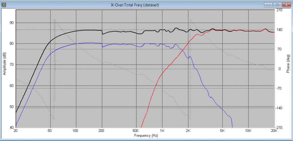
    Click image for larger version

Name:	Dimensions.jpg
Views:	1
Size:	64.6 KB
ID:	872311

    X-Over:
    Crossed at around 2100Hz.

    Click image for larger version

Name:	X-Over.jpg
Views:	1
Size:	35.7 KB
ID:	872313

    Freq. responce:

    Click image for larger version

Name:	Freq-response.jpg
Views:	1
Size:	58.3 KB
ID:	872312

    Click image for larger version

Name:	Inv-Freq-response.jpg
Views:	1
Size:	60.3 KB
ID:	872314
    DIY Audio °Roads Untraveled° to me,
    °In My Remains° , those who brought me °One Step Closer° to •The Story• of beautiful audio •Up In The Air•

    °Linkin Park° •30 Seconds to Mars•
  • Bear
    Super Senior Member
    • Dec 2008
    • 1038

    #2
    Fun project!
    Welcome to Rivendell, Mr. Anderson.

    Comment

    • BrechtVD
      Member
      • Aug 2014
      • 40

      #3
      I already started to build the enclosure.

      I did an 45° cut on al the edges expect for the back pannel that wil be removable.
      The enclosure will be build with 15mm multiplex.
      Will not add braces. Expect if someone tells me it is best to do so.

      Click image for larger version

Name:	20181226_170606 (Copy).jpg
Views:	1
Size:	70.9 KB
ID:	863869

      For the routing part I always draw the front baffle in a CAD program and print it on a 1:1 scale and gleu it on the wood. So I know the placement of the drivers, port, terminals, ... will be correct.
      The Peerless/Tymphany drivers are not completely round, I like that because you can get away with a pretty small baffle.
      But it is a pain for the routing part.

      First I did the round part as far as possible. Taking care I did not go to far.
      Then I routed a complete circle that just touches the straight edges of the Peerless drivers.

      Click image for larger version

Name:	20181226_170752 (Copy).jpg
Views:	1
Size:	76.6 KB
ID:	863866

      Next I need to take care of the straight edge.
      I clamped the baffle next to my fence of my table saw. So I knew it was in line.
      Then I adjusted my fence so my router just touches the complete circle.
      Next I started routing next to my fence of my table saw, with great care because I did not want to go to far...

      I am happy with the end result. One Tymphany/Peerless driver doesn't fit. The outher circle is just to small, that is next on my to do list.

      Click image for larger version

Name:	20181226_202254 (Copy).jpg
Views:	1
Size:	80.4 KB
ID:	863870

      Click image for larger version

Name:	20181226_202703 (Copy).jpg
Views:	1
Size:	63.4 KB
ID:	863867

      Click image for larger version

Name:	20181226_204010 (Copy).jpg
Views:	1
Size:	42.0 KB
ID:	863868
      DIY Audio °Roads Untraveled° to me,
      °In My Remains° , those who brought me °One Step Closer° to •The Story• of beautiful audio •Up In The Air•

      °Linkin Park° •30 Seconds to Mars•

      Comment

      • BrechtVD
        Member
        • Aug 2014
        • 40

        #4
        Next I had to chamfer the inside of the front baffle.
        Some room for the speakers

        Also hammered the M4 inserts in place for the tweeter and mid drivers.
        Click image for larger version

Name:	20181228_110537 (Copy).jpg
Views:	1
Size:	75.7 KB
ID:	863871

        Then I gleud it al together. At the back I tape it so I can fold it nicly together.
        An other advandace is that the wood gleu can only go to the inside. Of course only where you can tape it before folding it together.

        Click image for larger version

Name:	20181228_150808 (Copy).jpg
Views:	1
Size:	66.6 KB
ID:	863872

        I clamped it together. I also like to use wedges I screw to the table.

        Click image for larger version

Name:	20181228_153712 (Copy).jpg
Views:	1
Size:	80.6 KB
ID:	863873

        When the gleu was curing I soldered the X-over together.
        The wires sticking out wil be soldered to mid drivers and tweeters.

        Click image for larger version

Name:	20181228_194355 (Copy).jpg
Views:	1
Size:	102.6 KB
ID:	863874
        DIY Audio °Roads Untraveled° to me,
        °In My Remains° , those who brought me °One Step Closer° to •The Story• of beautiful audio •Up In The Air•

        °Linkin Park° •30 Seconds to Mars•

        Comment

        • BrechtVD
          Member
          • Aug 2014
          • 40

          #5
          Today I removed the clamps after approx 24h curing.
          Then I added chamfers to the front baffle with the table saw.
          15mm at the vertical sides from the front baffle and 7mm for the other edges.

          Click image for larger version

Name:	20181229_124240 (Copy).jpg
Views:	1
Size:	45.0 KB
ID:	863875

          I realised I best had to add braces in the enclosure.
          Sad I had to find that out at this point when it was gleud together.

          So I made 2 'brace panels' (don't know if this is really English...)
          I did this in 12mm Multiplex, that was what I had laying around.
          Also added a fillet at al the cutouts

          Click image for larger version

Name:	20181229_160331 (Copy).jpg
Views:	1
Size:	111.5 KB
ID:	863876

          Then I had to figer out how I would get it in the speaker enclousure.
          At the side I did a 20° cut aprox 5mm from the side (at the shortest side).
          So now I could gleu it in place.

          When gleuing I pushed the braces to the outside, with wedges.
          This way with the 20° cut I put pressure to each side I am gleuing.

          Because I don't want to push the enclosure open, I added a clamp at the top

          Click image for larger version

Name:	20181229_185223 (Copy).jpg
Views:	1
Size:	80.9 KB
ID:	863877

          Also gleud little corners in place that will hold the back pannel in place.
          This all will cure for aprox 24h

          Click image for larger version

Name:	20181229_190111 (Copy).jpg
Views:	1
Size:	86.9 KB
ID:	863878
          DIY Audio °Roads Untraveled° to me,
          °In My Remains° , those who brought me °One Step Closer° to •The Story• of beautiful audio •Up In The Air•

          °Linkin Park° •30 Seconds to Mars•

          Comment

          • wkhanna
            Grumpy Old Super Moderator Emeritus
            • Jan 2006
            • 5673

            #6
            fun looking project!!!!
            _


            Bill

            Practicing Curmudgeon & Audio Snob
            ....just an "ON" switch, Please!

            FinleyAudio

            Comment

            • BrechtVD
              Member
              • Aug 2014
              • 40

              #7
              First of all:
              Best wishes to everyone in 2019!

              Second: I got it running but it will need some little modifications.

              The day after I removed the clamps and wedges and to my own suprise the braces stayed nice in place.
              I sanded it a bit and added acoustic egg foam, everywhere I could.

              I placed the amp on the back panel because that way I take it all out and it is pretty easy to work on.
              And there was more work than i though =D

              The amp is good enough, you only have a bit noise that you hear if the volume is (almost) completely down.
              I think you will always have this with class D amps (correct me if I am wrong), at least with an amp of under 10USD

              Than I have a little fm-radio, bleutooth an aux module. The fm radio isn't that good, maybe add a decent antenna, now I was trying with just an aux cable. I bought an antenna with an aux connector (bit to short), therefore there is an aux connecter on the top.

              The aux is good without extra noise.

              Bluetooth is an other story, there is a high pitch noise when I use bleutooth... But if I power the little module with a isolated power supply from the amp the problem is solved.
              I was trying this with a battery just for the module. I will order an SIM2-1212 so I can use the same power supply from the amp but that way it will be isolated.

              Then I have a 'blop' when I turn my power on, I tried to add a 1uF (High pass filter of aprox 10Hz) at the input of the audio amp without succes.
              The chip used on the amp board has a standby mode that will work better but it isn't accessible on the amp board...
              Other idea's for this problem?

              Click image for larger version

Name:	20190102_124239 (Copy).jpg
Views:	1
Size:	48.2 KB
ID:	863886

              Click image for larger version

Name:	20190102_124501 (Copy).jpg
Views:	1
Size:	87.2 KB
ID:	863887

              I also added clear wood varnish and this is how they turned out.
              This is how they look. I am happy with the look and the sound. I have to say they are a bit bigger than I expected.

              I'll probably add a handle on top to take it around a bit easier XD

              Click image for larger version

Name:	20190102_124644 (Copy).jpg
Views:	1
Size:	32.9 KB
ID:	863888

              Click image for larger version

Name:	20190102_124715 (Copy).jpg
Views:	1
Size:	33.9 KB
ID:	863889
              DIY Audio °Roads Untraveled° to me,
              °In My Remains° , those who brought me °One Step Closer° to •The Story• of beautiful audio •Up In The Air•

              °Linkin Park° •30 Seconds to Mars•

              Comment

              • TEK
                Super Senior Member
                • Oct 2002
                • 1670

                #8
                Cool project.
                The bump sound is probably the amp that gets a signal during the power inrush. But sorry, do not know how to fix it.
                -TEK


                Many of the great achievements of the world were accomplished by tired and discouraged men who kept on working...

                Comment

                Working...
                Searching...Please wait.
                An unexpected error was returned: 'Your submission could not be processed because you have logged in since the previous page was loaded.

                Please push the back button and reload the previous window.'
                An unexpected error was returned: 'Your submission could not be processed because the token has expired.

                Please push the back button and reload the previous window.'
                An internal error has occurred and the module cannot be displayed.
                There are no results that meet this criteria.
                Search Result for "|||"