A 12 or 120 volt trigger for your pro amp

Collapse
This topic is closed.
X
X
 
  • Time
  • Show
Clear All
new posts
  • chasw98
    Super Senior Member
    • Jan 2006
    • 1360

    A 12 or 120 volt trigger for your pro amp

    This is a DIY project to build a device that will automatically turn on and off your "pro" amplifier. A lot of people around here have built subwoofers powered by pro amps like Crown, QSC, and Behringer. These pro amps have no way to be turned on or off remotely by either 12VDC or 120VAC "trigger" or "switched outlets" from AV equipment. These amplifiers also tend to draw a lot more current than your average AV receiver. Most solutions I have seen used by people are either way underated or prohibitively expensive.

    My Behringeer EP2500 has the capacity to draw 9.6 amps at full power according to the manual. At one point in time I had 2 EP2500's and 2 EP1500's plugged into the back of a monster HTS3500. I don't think it was meant to carry that kind of load. If we want to allow headroom so that the device does not heat up and burn out over time, we are looking at something that is rated at 12 amps or more per amplifier.

    We could use a mechanical relay with large capacity but they are bulky, mechanical, and noisy. They also have moving parts which tend to fail over time. Or we could use a device known as a "solid state relay" or SSR. This is a sold state version of the mechanical relay. It comes in a small package, can have current ratings in the 100's of amps, and are relatively inexpensive. SSR's are available with either DC or AC voltage control circuits.

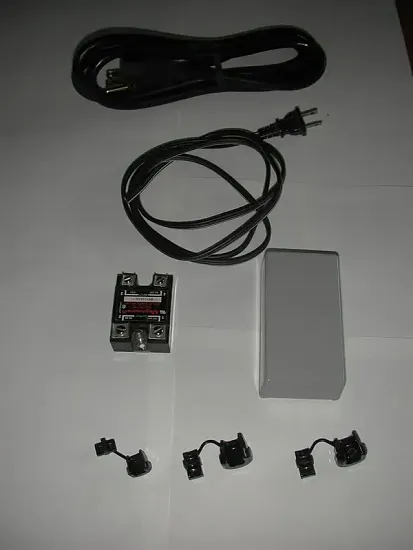
    The few parts needed are shown below. They consist of:

    01) - SSR from surplus or that auction place
    02) - Box to mount the SSR in from Mouser Electronics or Radio Shack
    03) - 18 AWG 2 conductor power cord for trigger
    04) - 14/3 power cord for amplifier current
    05) - Strain relief bushings to keep the cords in the box safely

    Click image for larger version

Name:	DSCN3903-1.webp
Views:	48
Size:	14.4 KB
ID:	939372

    To be continued............
    Last edited by theSven; 08 June 2023, 14:24 Thursday. Reason: Update image location
  • Bent
    Super Senior Member
    • Sep 2003
    • 1570

    #2
    that's a great and very reliable idea.

    I use a X-10 type switched outlet to power up my ADA 1200 plate amp, and for the most part it's relaible (but sometimes...)

    My Applied Digtal "Ocelot" is programmed to recognize the discrete IR "on" command from my remote control, and via If - THEN logic, switch on the outlet powering the ADA amp.

    It's convoluted and slightly complex, but since the ocelot is doing my lighting scenes as well as handling all of my IR macros, it was only logical to extend it's utility.

    Comment

    • chasw98
      Super Senior Member
      • Jan 2006
      • 1360

      #3
      Construction

      The first step in building this trigger box is to drill all the holes needed in the box. Number 2, mount the SSR into the enclosure. Strip the cables and insert the cables with the strain relief bushings is the last step in construction before wiring.

      If you use strain relief bushings, it won't be easy to put the holes in unless you have the punch tool, or access to a Bridgeport. You can just drill a round hole and they will work, but the strain relief bushings are meant to go into a "D" style hole so that rotation of the cable is not possible. There are other methods available such as electrical cable clamps or Hubbell strain reliefs. The 2 holes in the top of the enclosure are to mount the SSR inside.

      I have left the pictures large so that the detail can be shown, sorry to those on dial up.

      Click image for larger version

Name:	5-blank_box_1.webp
Views:	47
Size:	5.4 KB
ID:	939373

      Click image for larger version

Name:	6-blank_box_2.webp
Views:	32
Size:	6.3 KB
ID:	939374
      Last edited by theSven; 08 June 2023, 14:25 Thursday. Reason: Update image location

      Comment

      • chasw98
        Super Senior Member
        • Jan 2006
        • 1360

        #4
        Final Construction before wiring

        Here is a picture of the box with the SSR mounted and the strain reliefs holding the cables in place. What I have done is cut the 14 gauge power cord in half, then stripped about 4 to 5 inches off the ends. Put the AC plug half of the cord in the end with one hole. When putting the cord into the strain relief make sure and leave some of the outer sheath protruding from the end of the strain relief. It helps to have a big honkin' pair of slip joint pliers to squeeze down on that 14/3 and insert it into the box.

        After mounting the 14 gauge, I made sure that end of the 2 conductor trigger cord lined up with the end of the 14 gauge that would plug into the amp so that they are same length. You can always measure and adapt to your particular installation.

        Click image for larger version

Name:	8-prewired.webp
Views:	34
Size:	25.4 KB
ID:	939375
        Last edited by theSven; 08 June 2023, 14:25 Thursday. Reason: Update image location

        Comment

        • chasw98
          Super Senior Member
          • Jan 2006
          • 1360

          #5
          Wiring the components

          This is the final step, wiring the cables to the SSR for proper operation.

          DISCLAIMER: PLEASE REALIZE THAT YOU ARE WIRING A PROJECT TO BE USED WITH 120 VOLTS AC. THIS IS INHERENTLY DANGEROUS. IF YOU DO NOT FEEL COMFORTABLE DOING THIS ASK A FRIEND WHO IS FAMILIAR WITH AC WIRING TO HELP OR CONSULT AN ELECTRICIAN.

          STEP 1: Attach terminals to the ground wires of the 14 guage power cord and bolt them on to the screws that hold the SSR in place. This has the added benefit of grounding the case of the box should any wires ever become loose inside and touch the inside of the case.

          STEP 2: Attach terminals to the 2 conductor AC cord and screw them down to the terminals marked input. Polarity does not matter.

          Click image for larger version

Name:	7-ground_trigger_wired.webp
Views:	38
Size:	29.0 KB
ID:	939376

          STEP 3: Take the neutral wires and strip approx 1 inch from each wire. Slip a piece of heavy duty shrink tubing over the end of the longest piece. Place the stripped ends over each other and twist them together so that they make a good solid mechanical connection. Solder the bare wire. WAIT for the bare wire to cool and then slide the shrink tube over the joint and use a heat gun or a bic lighter to shrink the tube.

          STEP 4: Now you should have 2 "hot" leads left. 1 from each half of the 14 gauge power cord. Attach terminals to the ends and attach the ends to the remaining "output" terminals on the SSR.

          Click image for larger version

Name:	9-final_wired.webp
Views:	35
Size:	41.4 KB
ID:	939377
          Last edited by theSven; 08 June 2023, 14:27 Thursday. Reason: Update image location

          Comment

          • chasw98
            Super Senior Member
            • Jan 2006
            • 1360

            #6
            Final Testing

            Now that the box is wired, you can test it to see if it works. The first test is to make sure that no wires touch each other or make contact with the case of the box except the ground wires. I would definitely recommend using an ohmmeter to check for shorts or miswiring. After that, you may plug the 2 prong power cord into the switched outlet of your receiver or preamp, the SJE plug into your pro amp, and the 3 prong grounded cord into a live outlet. If there are no sparks, turn the power amp on (It should not turn on at this point). Then proceed to turn the receiver or preamp on. Your pro amp should turn on and off with the preamp turning on and off. Congratulations, you now have a high current trigger circuit. Before you finish up the box by screwing the cover on, I insulated the cover from the possibility of touching the terminals by using a piece of "fish paper" or stiff cardboard placed between the cover and the terminals. This can just as easily be done with electrical tape place inside the cover. Do a final check for shorts to ground and you are good to go.

            Click image for larger version

Name:	10-complete.webp
Views:	37
Size:	56.6 KB
ID:	939378
            Last edited by theSven; 08 June 2023, 14:27 Thursday. Reason: Update image location

            Comment

            • kgveteran
              Senior Member
              • Oct 2005
              • 865

              #7
              Here is a pair of switchers I built using 10amp delayed relays.There are four dedicated 20a lines from the main service panel.It turns on the line level stuff like all my PEQ's,BFD,Marchand BASSIS and then (3) B&K ST-140's,(4)QSC 1450's. All with the one trigger from my Outlaw 990.

              The key is the delays to avoid pops and enough current so the amps can breath.

              KG

              Total cost was about 120.00 at a local surplus store in town.

              Click image for larger version

Name:	sm trigger3.JPG
Views:	719
Size:	55.3 KB
ID:	846298

              Click image for larger version

Name:	sm trigger2.JPG
Views:	707
Size:	56.6 KB
ID:	846299

              Click image for larger version

Name:	sm trigger.JPG
Views:	731
Size:	56.5 KB
ID:	846300
              Last edited by theSven; 08 June 2023, 14:27 Thursday. Reason: Update image location
              Here is my LCR "Trio". Way to go guys !

              Comment

              • Inu_Yasha
                Senior Member
                • May 2006
                • 256

                #8
                I say this thread should be stickied or put in mission accomplished.

                Where did you get your relay box from, and also, how did you cut the metal casing?

                Comment

                • kgveteran
                  Senior Member
                  • Oct 2005
                  • 865

                  #9
                  Originally posted by Inu_Yasha
                  I say this thread should be stickied or put in mission accomplished.

                  Where did you get your relay box from, and also, how did you cut the metal casing?
                  The boxes were surplus and I had to hand cut all the holes with a dremel tool.The boxes were about 7.50 each.

                  The relays are 24vdc, so I had to pick up a 24vdc power supply to activate the relays.And there isn't even a hum.


                  BTW Chasw98, great project!
                  Here is my LCR "Trio". Way to go guys !

                  Comment

                  • chasw98
                    Super Senior Member
                    • Jan 2006
                    • 1360

                    #10
                    Some Final Thoughts and the Parts List

                    I have described an AC controlled trigger circuit. SSR's are available with DC control also, if you want to use a 12 volt DC trigger to turn the amp on and off. At the beginning I said to look for an approx 12 amp current rating on the SSR. I have never seen one with that rating. The 2 that I use at home have a rating of 25 amps and 40 amps respectively, more than enough to cover the draw of a pro amp or two.

                    I have used the Bud CU124 enclosure because it is made of .065 thick aluminum and acts as a heat sink for the SSR. I also used heat sink compound where the SSR mounted to the case to aid in heat dissipation. You will see advisories to use a heat sink if you are going to be drawing heavy loads near the rating of the SSR. In our case, I am not even sure it will get warm.

                    This is a silent foolproof way to turn your amp on and off remotely that will also allow full current from the wall outlet to reach your amp when it needs it. The AC cord I used is shielded but I don't know if that will make any difference in the sound or performance of your amp. I hope this has been helpful.

                    Here are the parts, their cost, and where I got them to build mine.


                    563-CU-124G Bud CU124G enclosure $9.50 each
                    836-1247 Heyco strain relief SR 7W-2 $0.22 each (2 needed)
                    836-1160 Heyco strain relief SR 6N-4 $0.17 each (1 needed)


                    17604/C3-25/10 Volex 17604 shielded 14/3 SJT power cord $6.00 each

                    dollar store
                    2 conductor 18 gauge extension cord for trigger cable $1.00

                    surplus electronics store
                    Magnetech or Crydom SSR 90-240 VAC input 240 VAC output 25 amps $12.00
                    (or find one at the auction site)

                    Total cost right around $30.00

                    Comment

                    • chasw98
                      Super Senior Member
                      • Jan 2006
                      • 1360

                      #11
                      Originally posted by kgveteran
                      Here is a pair of switchers I built using 10amp delayed relays.There are four dedicated 20a lines from the main service panel.It turns on the line level stuff like all my PEQ's,BFD,Marchand BASSIS and then (3) B&K ST-140's,(4)QSC 1450's. All with the one trigger from my Outlaw 990.

                      The key is the delays to avoid pops and enough current so the amps can breath.

                      KG

                      Total cost was about 120.00 at a local surplus store in town.
                      KG:
                      You didn't even let me finish writing out my project. Good looking boxes and circuits. I just pulled 4 20 amp circuits to my room also. I use my monster 3500 to do the time delays and startup for my equipment but I wanted full power to the amps EP2500, Earthquake 3 channel, Earthquake 5 channel.

                      Comment

                      • kgveteran
                        Senior Member
                        • Oct 2005
                        • 865

                        #12
                        I'm not sure i'd get a UL listing for mine, but it's worked in a wooden project box for about three years and I finally decided to put it in something that didn't look like it should be in a bomb squad scene in a movie :B

                        Sometimes my DIY stuff looks a little rough.I thought this turned out ok.
                        Here is my LCR "Trio". Way to go guys !

                        Comment

                        • kgveteran
                          Senior Member
                          • Oct 2005
                          • 865

                          #13
                          This all started with an article about one button turn on for your whole system.As you know older amps and pro gear don't have triggers......it's down in the basement we go...again :T .
                          Here is my LCR "Trio". Way to go guys !

                          Comment

                          • mazurek
                            Senior Member
                            • Mar 2006
                            • 204

                            #14
                            I use this: Xantech AC-1

                            i_ac1.pdf

                            I know its not DIY, but I like having a device not made by me in front of all of my home made electronics, it makes me feel safer.
                            Last edited by theSven; 08 June 2023, 14:28 Thursday. Reason: Attache PDF

                            Comment

                            • dynamowhum
                              Senior Member
                              • Aug 2006
                              • 260

                              #15
                              Man I thougt I was being farsighted and running 4 circuits to my new theater room. And here you guys make me realize I should have run 4 just to my equipment rack. I am glad I at least ran a 20 amp circuit to it.
                              Lets see if I cut in a new ceiling access panel etc.

                              Comment

                              • DeanP
                                Senior Member
                                • May 2004
                                • 175

                                #16
                                Hey maybe you guys could help me out here.
                                I just installed a dc trigger ssr in my chip amp but it makes my transformers buzz badly, when I remove the ssr,of course it goes away. It is a CRYDOM SOLID-STATE RELAY D2440-10 dc controlled(3-32vdc, rated to 240v / 40 amps. My trannys are 2x 400va dual 25v. Is the ssr faulty or should I get a mechanical type?
                                Just a note, I tried it out on my shop radio and I didn't seem to get any buzz.

                                Comment

                                Working...
                                Searching...Please wait.
                                An unexpected error was returned: 'Your submission could not be processed because you have logged in since the previous page was loaded.

                                Please push the back button and reload the previous window.'
                                An unexpected error was returned: 'Your submission could not be processed because the token has expired.

                                Please push the back button and reload the previous window.'
                                An internal error has occurred and the module cannot be displayed.
                                There are no results that meet this criteria.
                                Search Result for "|||"