
 Tweet
Tweet
In a couple of threads recently there has been some discussion as to how to create an active analog Cauer-Elliptic filter. I've made some up in a simulator and thought I'd share my results.
I haven’t got a clue how to run through the math to determine component values. Lancaster’s Active Filter Cookbook offers a hint, and even a topology for a second C-E order filter. He uses a state variable filter to make the notch, and the book offers no other notch. I plugged it into a circuit simulator and played with component values so I could see how it worked. The trouble with his second order was that I could not get Jon Marsh’s steep initial roll off and keep the bounce low enough to be useful. I had similar results with Jason Cuadra's topology.
Just as Butterworth Filter describes a response shape rather than a topology, Cauer-Elliptic filter describes a response that has a steep initial roll off and somewhere in the stop band the response rises to some level and ends up rolling off at the basic filter rate. For the purposes of an active XO, we want a response that meets Jon Marsh’s criteria - ~8th order LR initial roll off and a bounce that stays at least 50 db down.
Being a “rip off other people’s building blocks” artist, I figured I could get there with a fourth order filter and a notch filter. I used unity gain Sallen-Key topology. After spending the better part of a day on it, I got there.
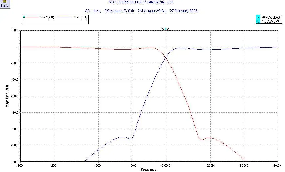
I started with a standard LR4 filter and found that the Q of the filter sections need to be much higher than standard because the notch causes a roll off earlier than expected. You’ll see a little ripple (~1 dB) either side of the XO, but that is the price you pay for the steep initial roll off.
Interestingly, as I was adjusting values to see which one has what impact on transfer function, I stumbled onto a curve that looked like Jon’s usual products with built in baffle step compensation. It didn’t match the baffles I was looking to use for a RS150/27TDFC MT, and after a few iterations, I gave up and went back to flat pass band response. I don’t have Jon’s aversion to op amps (obviously), so add another stage and be done with it.
I can’t offer a spreadsheet to generate C-E filters but the nutshell guidance when you sit down with a simulator is:
Start with a standard 4th order crossover topology with HP and LP sections followed by a notch filter of your choosing. (state variable, LCR, Active inductor, gyrator)
As Jon suggested, a notch about an octave away from the desired frequency works pretty well. It needs to be fairly high Q – I ended up at 6.5, with 32.5 dB of cut.
Set one section of your HP and LP filters to give an F3 of the desired crossover frequency with a Q of 1.6. Set the second section at 15% higher (for HP) or lower (for LP) with a Q of 1.7.
Play with filter component values to adjust the Q to reach the desired response. Increasing the F3 spread of the offset sections decreases pass band ripple, but you'll have to reduce the notch attenuation to compensate, making the bounce higher.
I haven't figured out how to sum responses or even display phase in the demo version of 5Spice I use, so this may not sum correctly. I'd appreciate any guidance.
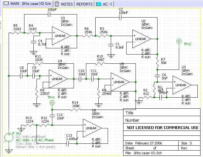
The schematic - a mess because the program is crippled by allowable drawing size. I didn't make a serious attempt to use component values that are actually available. The spreadsheet I use to calculate component values allows me to pick at least one capacitor per section, so you get some standard values
The resulting response:
I haven’t got a clue how to run through the math to determine component values. Lancaster’s Active Filter Cookbook offers a hint, and even a topology for a second C-E order filter. He uses a state variable filter to make the notch, and the book offers no other notch. I plugged it into a circuit simulator and played with component values so I could see how it worked. The trouble with his second order was that I could not get Jon Marsh’s steep initial roll off and keep the bounce low enough to be useful. I had similar results with Jason Cuadra's topology.
Just as Butterworth Filter describes a response shape rather than a topology, Cauer-Elliptic filter describes a response that has a steep initial roll off and somewhere in the stop band the response rises to some level and ends up rolling off at the basic filter rate. For the purposes of an active XO, we want a response that meets Jon Marsh’s criteria - ~8th order LR initial roll off and a bounce that stays at least 50 db down.
Being a “rip off other people’s building blocks” artist, I figured I could get there with a fourth order filter and a notch filter. I used unity gain Sallen-Key topology. After spending the better part of a day on it, I got there.
I started with a standard LR4 filter and found that the Q of the filter sections need to be much higher than standard because the notch causes a roll off earlier than expected. You’ll see a little ripple (~1 dB) either side of the XO, but that is the price you pay for the steep initial roll off.
Interestingly, as I was adjusting values to see which one has what impact on transfer function, I stumbled onto a curve that looked like Jon’s usual products with built in baffle step compensation. It didn’t match the baffles I was looking to use for a RS150/27TDFC MT, and after a few iterations, I gave up and went back to flat pass band response. I don’t have Jon’s aversion to op amps (obviously), so add another stage and be done with it.
I can’t offer a spreadsheet to generate C-E filters but the nutshell guidance when you sit down with a simulator is:
Start with a standard 4th order crossover topology with HP and LP sections followed by a notch filter of your choosing. (state variable, LCR, Active inductor, gyrator)
As Jon suggested, a notch about an octave away from the desired frequency works pretty well. It needs to be fairly high Q – I ended up at 6.5, with 32.5 dB of cut.
Set one section of your HP and LP filters to give an F3 of the desired crossover frequency with a Q of 1.6. Set the second section at 15% higher (for HP) or lower (for LP) with a Q of 1.7.
Play with filter component values to adjust the Q to reach the desired response. Increasing the F3 spread of the offset sections decreases pass band ripple, but you'll have to reduce the notch attenuation to compensate, making the bounce higher.
I haven't figured out how to sum responses or even display phase in the demo version of 5Spice I use, so this may not sum correctly. I'd appreciate any guidance.
The schematic - a mess because the program is crippled by allowable drawing size. I didn't make a serious attempt to use component values that are actually available. The spreadsheet I use to calculate component values allows me to pick at least one capacitor per section, so you get some standard values
The resulting response:
 ops:
ops:
Comment