Orion Rev.1 Mid-Woofer Mounting Question

Collapse
This topic is closed.
X
X
 
  • Time
  • Show
Clear All
new posts
  • RonS
    Senior Member
    • Jul 2004
    • 102

    Orion Rev.1 Mid-Woofer Mounting Question

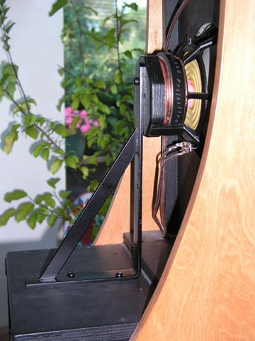
    Anyone know how SL mounts the W22 onto/into the wood block that is attached to the metal bracket? I'm building a dipole and would like to mount the midwoofers by their magnets, so that they don't actually touch the front baffle. I'd rather stay away from gluing the magnet assembly into a wood block if possible. Maybe some sort of clamping mechanism.

    Thanks,
    Ron

    Click image for larger version

Name:	magnet-mount.jpg
Views:	1132
Size:	54.8 KB
ID:	867469
    Last edited by theSven; 14 August 2023, 13:26 Monday. Reason: Update image location
  • Ten 99
    Senior Member
    • Apr 2004
    • 133

    #2
    I have no idea. Just examining the picture, it looks as though that is some sort of shelf bracket. The brack looks like it is attached via a screw to some hexagon part that looks like it is probably from ply or mdf. It looks like from there, there are two arms attached to the lower angled portions of the hex extending towards the driver. The driver's magnet has a black ring around it that gives the appearance to be reflective, but I'm not sure. I think I'm seeing the copper wire dangling over it reflecting into the black ring around the magnet. I was almost thinking at first though that the black ring might be of a felt or dampning nature. I don't know if the bracket is actually attached to the magnet, or if it is merely helping support the weight of the magnet from the rear. It's difficult to see.


    Attacking your situation with needing a clamping mechanism for the rear, the only thing I come up with at first shot in my mind, would also do a wonderfull job of blocking the reflective sound from the rear of the cone, and I'm pretty sure this would screw up the idea of the dipole setup.

    Just out of curiosity, why are you against physically mounting it to the baffle?

    Comment

    • robertwb70
      Member
      • Oct 2003
      • 59

      #3
      From the SL website-" mount the brackets, align and glue the drivers in place" and " the narrow gap between it and the baffle is sealed with a soft foam strip" and this is real interesting-"and exchange a resistor and capacitor in the crossover/equalizer."

      Why would you have to change electical parts for a different mounting method?
      Last edited by theSven; 14 August 2023, 13:32 Monday. Reason: Update text
      =+=+=+=+=+=+=
      "The appreciation of music is subjective.The reproduction of music isn't."-Bill Dudleston

      Comment

      • RonS
        Senior Member
        • Jul 2004
        • 102

        #4
        Originally posted by Ten 99
        Attacking your situation with needing a clamping mechanism for the rear, the only thing I come up with at first shot in my mind, would also do a wonderfull job of blocking the reflective sound from the rear of the cone, and I'm pretty sure this would screw up the idea of the dipole setup.
        Yup, that's definitely a prerequisite. That the clamping mechanism not block the rear wave. I have some ideas on how to do that, but wanted to see how SL did his.

        Originally posted by Ten 99
        Just out of curiosity, why are you against physically mounting it to the baffle?
        Mounting the driver directly transfers vibrations to the baffle. I've observed this in a prototype dipole that I've built, also see this study http://www.linkwitzlab.com/Driver%20Decoupling.doc by Andrew Jones of TAD/Pioneer. Just trying to reduce one more distortion.

        Ron

        Comment

        • Davey
          Senior Member
          • Jan 2003
          • 355

          #5
          Ron,

          If you're in the process of building did you consider using the rear-mount method of the Phoenix system? This would seem to be preferrable to the Orion mounting scheme. There still needs to be a rear support of some kind, but since it wouldn't have to support much weight it could be fairly unobtrusive.
          The Rev 1 mounting method for the Orion appears to be a "fix" that is useful only since the front baffle mounting (front rebate) was scheme was used. Mounting from the rear would also give a much "cleaner" look to the front of the speaker.

          This revision to the Orion is a bit mysterious to me since it seems to affirm/contradict many of the design issues that SL has previously let go by. I haven't performed this update on my Orion's so I don't know how audible the improvement is, but I know that super solid baffles and driver mounting is one of those things that DIY'ers strive for so the Orion system must have bugged the crap out of many DIY speaker builders.

          The "resistor and capacitor in the crossover/equalizer" is a -0.5db change to the notch depth in the midrange EQ filter. Apparently the bracket addition effects the polar response of the system slightly and SL felt this was necessary.

          Cheers,

          Davey.

          Comment

          • RonS
            Senior Member
            • Jul 2004
            • 102

            #6
            Davey,

            I am actually using a variation of the Phoenix style rear mounting (spent 3hrs. yesterday in the shop cutting baffles). I wanted to avoid three things that I didn't like about the Phoenix, 1 is the added depth to the speakers (I want everything to be contained within the depth of the side wings), 2 is that I want the mounting bracket to be more "open", thereby avoiding blocking the rear wave launch as much as possible. Of course the M8a woofers that I'm using aren't much of an open design on the back compared to say the Vifa MG22 woofers that I have. The 3rd thing is that I think the Phoenix still couples the woofer too well to the baffle, as it is under compression. I would prefer to mount the woofer from the magnet only, and have it barely touch the front baffle (using foam gasket) so that it is literally floating behind the baffle. Hope this is clear.

            Click image for larger version

Name:	magnet-mount.jpg
Views:	4086
Size:	93.5 KB
ID:	841068

            This is my current thinking, quick "napkin" drawing and coloured in PS. Basically the magnet is clamped between the 2 halves of the MDF donut using hose clamps. The donut halves are mounted to L-shaped aluminium profiles, who in tern mount to mdf blocks on the sides of the wings. There is rubber around the magnet structure. I don't know if this would have enough strength to hold the woofer, but if it did, the woofer would literally be floating just behind the baffle, only lightly touching the foam gasket tape. Very open design, and the woofer doesn't get glued permenantly to anything.

            Thoughts?
            Last edited by theSven; 14 August 2023, 13:27 Monday. Reason: Update image location

            Comment

            • Dennis H
              Ultra Senior Member
              • Aug 2002
              • 3791

              #7
              Personally, I'd go for a much simpler (and cleaner) solution if I were building from scratch. SL's deal is okay for a retrofit but it looks kludgy for new construction. First start with a beefy baffle, possibly a constrained layer construction. Use the normal driver mounting holes but don't allow any metal of the frame or the fasteners to touch wood - oversize rabbets, lots of gasket material, through bolts with oversize holes, nuts with sorbathane washers, etc. It would be much easier with a dipole than with a box speaker because you could get at the back side to install the nuts.

              Comment

              • Davey
                Senior Member
                • Jan 2003
                • 355

                #8
                Ron,

                Your napkin design looks pretty good. I don't know why that wouldn't work effectively, and it also seems to satisfy your requirement for minimum mounting depth. Can you post some photos when built?

                Davey.

                Comment

                • RonS
                  Senior Member
                  • Jul 2004
                  • 102

                  #9
                  Davey,

                  After I drew this out, I realized that it bears some resemblance to the Klippel test fixture. I swear I wasn't copying! My only concern is how much preasure to put on the magnet, don't want to crack it!

                  Of course I'll post some pics when I'm done. Right now I've got the front baffles cut out and ready for the drivers. I still have to cut out the wings, and build the whole driver mounting thing.

                  By the way, I'm planning on using the DCX2496 crossover for this guy, mated to a small sealed sub (the room is too small to support dipole bass unfortunately). I'll be using an 8th order L-R between the M8a and the XT25 tweeter, sort of like JonM does in his passive versions, at 1.25kHz.

                  Ron

                  Comment

                  • Ten 99
                    Senior Member
                    • Apr 2004
                    • 133

                    #10
                    Baffles, and clamping.

                    I agree with what Dennis said. To me it seems much easier to rethink the simpler things. I think it's easy to get tunnel vision at times, and when one thinks of seperating the connection to the baffle (decouple I suppose) via the foam and no mounting screws, and using a rear bracket attaching to the magnet structure to accomplish this... well, it gets convoluted to me. I think I would try making a better baffle.

                    Drivers make vibrations because that's what they do. Baffles (traditionally) hold the drivers via mounting screws. If the Baffles are having a tendancy to vibrate and muddy the sound either detected by ear or electronic measuring device, then why not build a better baffle? I would almost think that a more rigid baffle would help. What about Corian material? This is some stiff, heavy, ridgid, and very machinable stuff! I like the idea about using gaskets beteen the driver and the baffle made from sorbathane. I think you could further use washers made of sorbathane or some other rubber material to dampen the vibrations between driver, mounting hardware, and the baffle. I would think it would at least be worth a shot.

                    You could probably get a "cutout" section from a kitchen sink for next to nothing, to make a small test baffle out of, and then make a same dimensional baffle out of MDF, and then put the same driver using the same hardware in each baffle, and then take measurements to detect the differences that each baffle creates.

                    Now, should you go back to the though of the clamp/bracket for the magnet structure... How about taking a similar sized PVC tube as the magnet OD, and rip a straight line via a table saw down the vertical length of the PVC. Now you have a big "C" of sorts. You could use large hose clamps, even piggybacking them if extra length is needed in order get around it. The length of this "C" PVC clamp is whatever you need it to be. If you couldn't find PVC similar in size, you might consider a plastic material that I've seen called Kydex. It is used to make holsters and the like. It is heat formable, and when it cools it retains it's shape. a "C" clamp could be made from a sheet of this stuff by heating it and slowing rolling and forming it around the circum. of the magnet.

                    Comment

                    • RonS
                      Senior Member
                      • Jul 2004
                      • 102

                      #11
                      Ten 99,

                      If you read the article I mentioned earlier, you'll see that rigid mounting of the driver to the baffle is not a good thing. However, decoupling of the driver in the way that you suggest doesn't sound like a good idea to me either. Now we have this huge mass, with a strong motor, flopping about on some sorbothane or such. Intuitively, mounting the driver by it's magnet/motor seems like the better approach. In that case, the only thing I can see moving is the cone, which is the only part that is supposed to vibrate.

                      I don't think I'm getting tunnel vision at all, the exact opposite I'd say. Why continue to do what everyone has always done, because it is the norm? It's not necessarily the best way (not that my suggestion is either, it's just an idea that I think is worth pursuing).

                      As always, any comments are welcome.

                      Ron

                      Comment

                      • Dennis H
                        Ultra Senior Member
                        • Aug 2002
                        • 3791

                        #12
                        Now we have this huge mass, with a strong motor, flopping about on some sorbothane or such.
                        Well, that's sort of the definition of decoupling. If you mount it solidly by the magnet, vibrations will get transmitted to the panel by your framework instead of by the basket and you have gained nothing. If you don't mount it solidly, it will "flop around." You can't have it both ways.

                        But, putting it all in perspective what really counts is the ratio of the moving mass to the fixed mass. In the case of the HiVi driver, that ratio is quite low so the basket and magnet will move little, even if the driver is totally decoupled, e.g. hanging from a string.

                        Comment

                        • RonS
                          Senior Member
                          • Jul 2004
                          • 102

                          #13
                          Originally posted by Dennis H
                          Well, that's sort of the definition of decoupling. If you mount it solidly by the magnet, vibrations will get transmitted to the panel by your framework instead of by the basket and you have gained nothing. If you don't mount it solidly, it will "flop around." You can't have it both ways.
                          My suspicion is that there will be less vibration by mounting the magnet rather than the basket. Something about greater mass, momentum, I'm not sure. Guess I'll find out once I do it.

                          Originally posted by Dennis H
                          But, putting it all in perspective what really counts is the ratio of the moving mass to the fixed mass. In the case of the HiVi driver, that ratio is quite low so the basket and magnet will move little, even if the driver is totally decoupled, e.g. hanging from a string.
                          Well, if the ratio of moving mass to fixed mass is so great, then why are there vibrations transmitted to the the baffle when I solidly mount the woofer to the baffle? I mean, it makes sense to me, very light cone/voice coil, how could this move the heavy magnet/basket? But it does.

                          It would be interesting to do a test, 3 different scenarios (sp?), basket mounting, woofer mounting, and totally decoupling by basket. Measure vibrations. I don't have the time to do that though.

                          Cheers,
                          Ron

                          Comment

                          • RonS
                            Senior Member
                            • Jul 2004
                            • 102

                            #14
                            Proof of Concept

                            I've got a pair of my motor mounts built. I had a woofer mounted in one of them last night, it felt pretty solid in my hands. Tonight I'll mount them into the baffles, and hopefully have time to do some testing later this week.

                            Click image for larger version

Name:	IMG_3419a.jpg
Views:	3809
Size:	54.0 KB
ID:	841292

                            Here's a shot of the front. 1/8" sorbothane will line the inside of the MDF "donut", which clamps around the magnet of the M8A woofer.

                            Click image for larger version

Name:	IMG_3420a.jpg
Views:	3866
Size:	55.2 KB
ID:	841293

                            Here's a shot of the back side (which actually faces the front of the speaker). Didn't have anything handy that could cut those stainless steel pipe clamps, so the extra just hangs there.

                            I sure hope this whole idea works, because making those motor mounts was a pain in the rear. A lot of work, especially machining the MDF parts.

                            I'm going to start a new thread in the next day or two about the speaker, as I make more progress.
                            Last edited by theSven; 14 August 2023, 13:27 Monday. Reason: Update image location

                            Comment

                            • JonMarsh
                              Mad Max Moderator
                              • Aug 2000
                              • 15254

                              #15
                              Interesting looking hardware you've put together there, Ron. I'll be curious to see the results of your testing and your comments.

                              Regards,

                              Jon
                              the AudioWorx
                              Natalie P
                              M8ta
                              Modula Neo DCC
                              Modula MT XE
                              Modula Xtreme
                              Isiris
                              Wavecor Ardent

                              SMJ
                              Minerva Monitor
                              Calliope
                              Ardent D

                              In Development...
                              Isiris Mk II updates- in final test stage!
                              Obi-Wan
                              Saint-Saƫns Symphonique/AKA SMJ-40
                              Modula PWB
                              Calliope CC Supreme
                              Natalie P Ultra
                              Natalie P Supreme
                              Janus BP1 Sub


                              Resistance is not futile, it is Volts divided by Amperes...
                              Just ask Mr. Ohm....

                              Comment

                              • RonS
                                Senior Member
                                • Jul 2004
                                • 102

                                #16
                                Hi Jon,

                                My goals with this "hardware" were to eliminate transmission of any vibrations to the baffle as well as eliminating basket flex (which I think I would have got if I mounted the woofer by the traditional means), and to mount the woofers in such a way as to not permanently damage them (SLs revised Orion system glues the woofers to their brackets, yuck). I also wanted a very open design, although I don't really feel that the M8A is a very open speaker to start with.

                                We'll see how effective the sorbothane is. Anyone have an accelerometer they could lend me?

                                Ron

                                Comment

                                • RonS
                                  Senior Member
                                  • Jul 2004
                                  • 102

                                  #17
                                  Here it is, the first speaker done (well, I still have to put a 3/4" roundover on the two vertical edges and veneer the thing).

                                  Front shot

                                  Click image for larger version

Name:	IMG_3423.jpg
Views:	3761
Size:	65.0 KB
ID:	841295

                                  Back

                                  Click image for larger version

Name:	IMG_3424.jpg
Views:	4050
Size:	75.1 KB
ID:	841296

                                  Close up showing the mounting detail

                                  Click image for larger version

Name:	IMG_3425.jpg
Views:	3862
Size:	79.2 KB
ID:	841297

                                  Testing begins next Tuesday!

                                  Ron
                                  Last edited by theSven; 14 August 2023, 13:28 Monday. Reason: Update image location

                                  Comment

                                  • Davey
                                    Senior Member
                                    • Jan 2003
                                    • 355

                                    #18
                                    Nice looking mounting scheme Ron. The HiVi drivers make for a very attractive looking speaker from the front eh?

                                    Davey.

                                    Comment

                                    • Evil Twin
                                      Super Senior Member
                                      • Nov 2004
                                      • 1531

                                      #19
                                      Very nice work, Ron! I can't help but think that this mounting will work much better than, for instance, the original Phoenix! A lot less obstruction of the rear wave, and should couple minimally into the front baffle.

                                      We await your report on the acoustical results....
                                      DFAL
                                      Dark Force Acoustic Labs

                                      A wholly owned subsidiary of Palpatine Heavy Industries

                                      Comment

                                      • RonS
                                        Senior Member
                                        • Jul 2004
                                        • 102

                                        #20
                                        Davey,

                                        Yup, those HiVi drivers sure do look pretty! I must say though that I'm not thrilled with the aesthetics of the speaker itself. I used SLs dimensions for width of the panel (12.5" wide) and cut it down to 24" high to fit a standard 2x4' MDF sheet. I'm hoping that the 3/4" roundover will soften the look of the speaker. A narrower panel would have looked better.

                                        Jon,

                                        As you know, those were two of my design requirements for this speaker. Now the hard part comes, the crossover design! I was originally going to go passive, but I'm really tempted to do a digital DCX2496 crossover.

                                        I'll post more as I go along.

                                        Ron

                                        Comment

                                        • Davey
                                          Senior Member
                                          • Jan 2003
                                          • 355

                                          #21
                                          I dunno Ron. I think they look pretty good. Beauty is in the eye I guess.

                                          Will you ultimately glue the side panels vice the screws?

                                          I have DCX2496 setup files for a variety of the Linkwitz systems. They would be a good starting point for your setup. Give me a holler and I will email them.

                                          Best,

                                          Davey.

                                          Comment

                                          • RonS
                                            Senior Member
                                            • Jul 2004
                                            • 102

                                            #22
                                            Davey,

                                            The side panels are glued on. I used the screws because I don't have enough clamps. I'll eventually remove all of the scews and fill the holes with wood filler, and put a 3/4" radius on the vertical edges and veneer over that.

                                            I guess I'm just not used to seeing such a wide speaker in my room, my current setup is a small 2 way stand mounted box.

                                            I'd appreciate copies of your DCX2496 setups, you can email them to me at ron.steinberg@sympatico.ca

                                            Thanks!

                                            Ron

                                            Comment

                                            • RonS
                                              Senior Member
                                              • Jul 2004
                                              • 102

                                              #23
                                              Well, here's the first test. Done at 1M (I was getting too many reflections at 2M), speaker centre is 75" off the ground. The impedence plot clearly shows the 2kHz peak, but nothing at 6600Hz, so I'm assuming this is acoustic only. No smoothing applied, this is the pair of M8As only. Comments?

                                              Click image for larger version

Name:	M8a@1m o.jpg
Views:	3474
Size:	84.8 KB
ID:	841304
                                              Last edited by theSven; 14 August 2023, 13:28 Monday. Reason: Update image location

                                              Comment

                                              • Davey
                                                Senior Member
                                                • Jan 2003
                                                • 355

                                                #24
                                                Ron,

                                                It looks good and pretty much as expected. Did you take some off-axis measurements?

                                                Davey.

                                                Comment

                                                • RonS
                                                  Senior Member
                                                  • Jul 2004
                                                  • 102

                                                  #25
                                                  Davey,

                                                  Here's the off axis measurements, taken this morning.

                                                  Click image for larger version

Name:	M8aoffax.jpg
Views:	3447
Size:	98.7 KB
ID:	841305

                                                  I'm about to do some nearfield measurements to investigate the 6.6kHz peak.

                                                  I'm not seeing the dipole hump at 400Hz as clearly at the 1M distance as I did at 2M, but then again, it's a lot cleaner at 1M. I'll go back to doing some 2M measurements as well, probably to do the PEQ.

                                                  Cheers,
                                                  Ron
                                                  Last edited by theSven; 14 August 2023, 13:28 Monday. Reason: Update image location

                                                  Comment

                                                  • RonS
                                                    Senior Member
                                                    • Jul 2004
                                                    • 102

                                                    #26
                                                    Here's a 1M vs. 2M measurement. As you can see, the area around 600Hz is quite different, at 2M there's a pretty big dip. I'm not sure if I should equalize for the 1M or the 2M. The 1M seems easier to work with, especially in picking the relative level of the driver. Anyone have any input on what is causing the dip at 600Hz?

                                                    Ron

                                                    Click image for larger version

Name:	1M vs. 2M.jpg
Views:	3497
Size:	82.3 KB
ID:	841306
                                                    Last edited by theSven; 14 August 2023, 13:29 Monday. Reason: Update image location

                                                    Comment

                                                    • JonMarsh
                                                      Mad Max Moderator
                                                      • Aug 2000
                                                      • 15254

                                                      #27
                                                      Where did you make your measurements? Out doors? In room? How far farm nearest boundary? Gating time?

                                                      I've rarely seen it possible to get good indoor 2 m measurements unless it's a pretty large room. Of course, in the real world, you have to live with whatever your room has got and does- or compensate as feasible. What's the baffle width and the net dipole path difference?

                                                      BTW, I've always used offset mounting of the midwoofers in my experiments since 2001, like this guy, I've found it's smoother overall, perhaps becuase of distributing the bumps- found golden mean ratios to work well.


                                                      ~Jon
                                                      Last edited by theSven; 14 August 2023, 13:30 Monday. Reason: Update url
                                                      the AudioWorx
                                                      Natalie P
                                                      M8ta
                                                      Modula Neo DCC
                                                      Modula MT XE
                                                      Modula Xtreme
                                                      Isiris
                                                      Wavecor Ardent

                                                      SMJ
                                                      Minerva Monitor
                                                      Calliope
                                                      Ardent D

                                                      In Development...
                                                      Isiris Mk II updates- in final test stage!
                                                      Obi-Wan
                                                      Saint-Saƫns Symphonique/AKA SMJ-40
                                                      Modula PWB
                                                      Calliope CC Supreme
                                                      Natalie P Ultra
                                                      Natalie P Supreme
                                                      Janus BP1 Sub


                                                      Resistance is not futile, it is Volts divided by Amperes...
                                                      Just ask Mr. Ohm....

                                                      Comment

                                                      • RonS
                                                        Senior Member
                                                        • Jul 2004
                                                        • 102

                                                        #28
                                                        The measurements were done in my 2000 square foot photo studio. Closest side wall or pillar was 10'. Tweeter was 6'4" off the ground, so the floor bounce precedes any wall bounce.

                                                        1M window was 7.76ms, while the 2M was 5.89ms.

                                                        Baffle width is 12.5", with a net path difference of 16.75".

                                                        I was thinking of offsetting the woofers and tweeters, but wanted to keep the baffle width to 12.5" for aesthetic reasons (this is also the minimum width that I can make a stacked Wframe woofer system, which will be the bass for the midrange panel). Theres just no room to move that woofer over, with the unique mounting technique I'm using. I'll be using felt around the tweeter.

                                                        Cheers,
                                                        Ron

                                                        Comment

                                                        • RonS
                                                          Senior Member
                                                          • Jul 2004
                                                          • 102

                                                          #29
                                                          Here's a shot of the test setup. The white cart on the right holds the laptop and IMP system. The mic is barely visible, it's the brass wand with the red strips on it.

                                                          Click image for larger version

Name:	IMG_3449.jpg
Views:	3566
Size:	80.0 KB
ID:	841307
                                                          Last edited by theSven; 14 August 2023, 13:31 Monday. Reason: Update image location

                                                          Comment

                                                          • JonMarsh
                                                            Mad Max Moderator
                                                            • Aug 2000
                                                            • 15254

                                                            #30
                                                            I'm jealous of your room, Ron!

                                                            No easy suggestions come to mind; I understand the desire to keep your baffles petite.

                                                            I'll give you more feedback when I get the off axis measurements done on my Arvos. Got another biz trip next week, so probably won't look at more measurements before the weekend after next.

                                                            ~Jon
                                                            the AudioWorx
                                                            Natalie P
                                                            M8ta
                                                            Modula Neo DCC
                                                            Modula MT XE
                                                            Modula Xtreme
                                                            Isiris
                                                            Wavecor Ardent

                                                            SMJ
                                                            Minerva Monitor
                                                            Calliope
                                                            Ardent D

                                                            In Development...
                                                            Isiris Mk II updates- in final test stage!
                                                            Obi-Wan
                                                            Saint-Saƫns Symphonique/AKA SMJ-40
                                                            Modula PWB
                                                            Calliope CC Supreme
                                                            Natalie P Ultra
                                                            Natalie P Supreme
                                                            Janus BP1 Sub


                                                            Resistance is not futile, it is Volts divided by Amperes...
                                                            Just ask Mr. Ohm....

                                                            Comment

                                                            • RonS
                                                              Senior Member
                                                              • Jul 2004
                                                              • 102

                                                              #31
                                                              Yup, that room is nice for measurements, when it's not all filled with photo shoot junk! It extend's another 10' to the right of the wood column (next to the computer) too Too bad it's not my listening room, which is actually a tiny 12x14' thing. I know, I know, way too small for dipoles. That's why I'm only doing dipole to around 100Hz, and sealed sub below that.

                                                              Davey suggested that I test another speaker at 2M to see if I get the same dip at 600Hz, it could be a reflection from something, although I'm pretty sure I windowed it properly. We'll see.

                                                              I'm pretty happy with the off axis response, looks nice and smooth. More measurements this weekend hopefully, try to figure out the 600Hz thing, and work on the tweeter (need to add felt for diffraction control).

                                                              Cheers,
                                                              Ron

                                                              Comment

                                                              Working...
                                                              😀
                                                              😂
                                                              🥰
                                                              😘
                                                              🤢
                                                              😎
                                                              😞
                                                              😡
                                                              👍
                                                              👎
                                                              Searching...Please wait.
                                                              An unexpected error was returned: 'Your submission could not be processed because you have logged in since the previous page was loaded.

                                                              Please push the back button and reload the previous window.'
                                                              An unexpected error was returned: 'Your submission could not be processed because the token has expired.

                                                              Please push the back button and reload the previous window.'
                                                              An internal error has occurred and the module cannot be displayed.
                                                              There are no results that meet this criteria.
                                                              Search Result for "|||"